


10
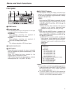
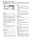
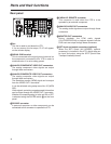
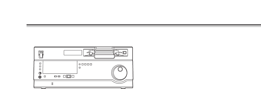
Front panel
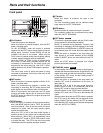
VDIAG button
When this button is pressed, the VTR information is
displayed.
When it is pressed again, the original display is
restored.
The VTR information consists of the HOURS
METER information and WARNING information.
Switching between the display of each type of
information is accomplished by pressing the search
button.
Displayed on the HOURS METER screen are the
deck’s serial number, power-on time, drum rotation
time, tape travel time, number of times a cassette
has been loaded, number of times the power has
been turned on and off, and so on.
Displayed on the WARNING screen are details of
the warnings.
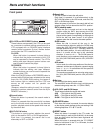
WSUPER switch
ON:
The superimposed time code and other
information is output to the VIDEO OUT 3
connector or SDI OUT 3 connector.
OFF:
The superimposed information is not output.
XREC INH switch
This switch is used to enable or disable recording
on the cassette tape.
ON:
Recording on the cassette tape is disabled
(inhibited).
In this state, the REC INH lamp lights on the
display panel.
OFF:
Recording on the cassette tape is enabled so
long as the accidental erasure prevention
mechanism on the cassette tape is set to enable
recording.
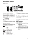
Parts and their functions
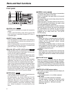
YTCG switch
REGEN:
The internal time code generator is synchronized
with the time code which the time code reader
has read from the tape.
The signal that is to be used for regeneration is
selected using setup menu No. 503 (TCG
REGEN).
PRESET:
The time code generator can be preset on the
operation panel or by remote control.
EXT:
The external time code which is input from the
time code input connector or video signal VITC is
used. Which of the two is to be set is selected
using setup menu No. 505 (EXT TC SEL).
ZMODE switch
<In the stop mode>
TAPE:
The signal which is played back from the tape is
output.
EE:
The input signal selected by the INPUT SELECT
button is output.
<During recording or editing>
TAPE:
The simultaneous playback signals are output.
(The setup menu No.310 (CONFI EDIT) setting
is necessary.)
EE:
The input signal selected by the INPUT SELECT
button is output.
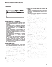
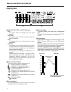
[CONTROL switch
This switch is set to the REMOTE or LOCAL
position when the VTR is to be controlled by an
external unit using the REMOTE, RS-232C or
PARALLEL connector.
REMOTE:
Set the switch to this position to control the VTR
using a component that has been connected
using the 9-pin REMOTE, RS-232C or
PARALLEL connector.
LOCAL:
Set the switch to this position to control the VTR
using its operation panel.
When the unit is to be controlled with the switch
at this position by a component connected using
the PARALLEL connector, selection can be
made using setup menu No. 211 (LOCAL 25P).