


43
Setup menus
The underlined items indicates the initial setting.
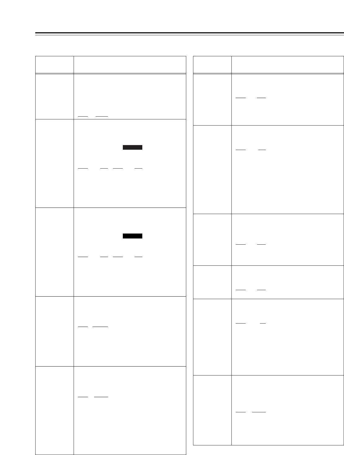
USER menu
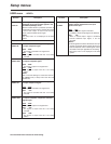
<TIME CODE>
No./Item Description
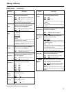
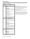
506
BINARY GP
This sets the usage status of the user bit of
the time code generated by the TCG.
0000 000
:
NOT SPECIFIED (character set not specified)
0001 001
:
ISO CHARACTER (8 bits character set based
on ISO646, ISO2022)
0002 010
: UNASSIGNED 1 (undefined)
0003 011
: UNASSIGNED 2 (undefined)
0004 100
: UNASSIGNED 3 (undefined)
0005 101
: PAGE/LINE
0006 110
: UNASSIGNED 4 (undefined)
0007 111
: UNASSIGNED 5 (undefined)
507
PHASE CORR
This selects whether to control the phase
correction of the LTC which is output from
the TIME CODE OUT connector.
0000
OFF
:
Phase correction control is not performed.
0001 ON
:
Phase correction control is performed.
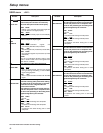
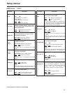
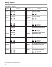
508
TCG CF FLAG
This selects whether the CF flag of the TCG is
to ON.
0000 OFF
: CF flag is OFF.
0001 ON
: CF flag is ON.
509
DF MODE
This selects the DF or NDF mode for CTL and
TCG.
0000 DF
: The drop frame mode is used.
0001 NDF
: The non-drop frame mode is
used.
<Notes>
ODrop frame mode is valid only when the
CONTROL switch is set to LOCAL or the setup
menu No. 001 (LOCAL ENA) is set to ENA.
OThis setup menu is not displayed in the 625i
system.
510
TC OUT REF
This is used to switch the phase of the time
code, which is output from the TIME CODE
OUT connector, for the external LTC input
when the TCG switch is at the EXT position.
0000 V OUT
:
Time code is synchronized with output video
signal.
0001 TC_IN
:
Time code is synchronized with external time
code input.
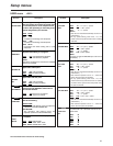
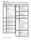
No./Item Description
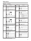
500
VITC BLANK
For selecting whether to output the VITC
signal at the positions selected by setup
menu items No. 501 (VITC POS-1) and No. 502
(VITC POS-2).
0000 BLANK
: VITC signals are not output.
0001 THRU
: VITC signals are output.
501
VITC POS-1
This sets the position where the VITC signal
is to be inserted.
[525i system] [625i system]
0000 10L 0000 7L
::::
0006
16L 0004 11L
::::
0010 20L 0015 22L
<Note>
The same line as the one used for the setup
menu item No. 502 (VITC POS-2) setting cannot
be set.
SD955A
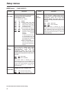
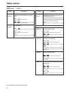
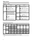
503
TCG REGEN
This selects the signal to be regenerated
when the time code generator (TCG) in the
REGEN mode.
0000 TC&UB
:
Both the time code and user bit are
regenerated.
0001 TC
:
Only the time code is regenerated.
0002 UB
:
Only the user bit is regenerated.
504
REGEN MODE
This selects whether the time code is to be
regenerated during automatic editing using
the unit’s control panel.
0000 AS&IN
:
Time code is regenerated with assemble or
insert editing.
0001 ASSEM
:
Time code is regenerated with assemble
editing.
0002 INSRT
:
Time code is regenerated with insert editing.
0003 SW
:
Setting complies with TCG switch setting.
505
EXT TC SEL
This selects the time code to be used when
an external time code is to be used.
0000 LTC
:
The LTC of the TIME CODE IN connector is
used.
0001 VITC
:
The VITC of the input video signal is used.
502
VITC POS-2
This sets the position where the VITC signal
is to be inserted.
[525i system] [625i system]
0000 10L 0000 7L
::::
0008
18L 0006 13L
::::
0010 20L 0015 22L
<Note>
The same line as the one used for the setup
menu item No. 501 (VITC POS-1) setting cannot
be set.
SD955A