


14
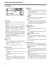
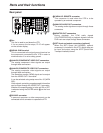
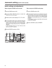
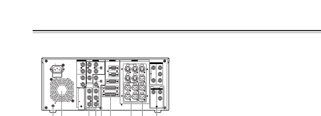
Rear panel
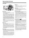
<Fan
This fan is used to cool down the VTR.
If, for any reason, the fan stops, “E-10” will appear
on the counter display.
=SIGNAL GND terminal
This is connected to the signal ground terminal on
the component connected to this VTR in order to
minimize noise. It is not a safety ground.
>ANALOG COMPONENT VIDEO OUT connectors
The analog component video signals are output
through these connectors.
?ANALOG COMPOSITE VIDEO OUT connectors
The analog composite video signals are output
through these connectors.
The waveform monitor (WFM) signal can be output
from the VIDEO OUT 2 connector.
It can be selected using setup menu No. 00 (WFM
SEL).
Video signals containing superimposed information
can be output through the VIDEO OUT 3 connector.
Whether the superimposing is to be set ON or OFF
is selected using the SUPER switch W on the front
panel.
@RS-232C connector
A personal computer or other component can be
connected to this connector to operate the VTR.
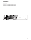
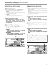
Parts and their functions
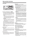
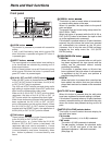
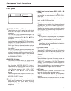
APARALLEL REMOTE connector
This connector is used when the VTR is to be
operated by an external component.
BANALOG AUDIO OUT connectors
The analog audio signals are output through these
connectors.
CMONITOR OUT connectors
During playback, the PCM audio signals
(CH1/CH2/CH3/CH4) or playback signals from the
CUE track are output through these connectors.
DSDTI input and output connectors (optional)
When the SDTI board (AJ-YAC930G, optional
accessory) is installed in this VTR, digital data can
be input and output using the SDTI (Serial Data
Transport Interface) format.
PUSH PUSH
PUSH PUSH
PUSH
AC IN
SIGNAL
GND
AES/EBU
SDI
SDTI
ANALOG
CH1/2
IN
Y
VIDEO
VIDEO
OUT
SERVICE ONLY
REMOTE IN/OUT
CH1 CH2AUDIO
IN
ENCODER REMOTE
RS-232C
PARALLEL
REMOTE OUT
IN
REF VIDEO
IN
ON
OFF
P
B
P
R
Y1
2
(WFM)
3
(SUPER)
P
B
P
R
OPTION
CH3/4
IN
CH1/2
OUT
CH3/4
OUT
REMOTE
75Ω
ON
OFF
75Ω
ANALOG
TC
IN
IN
ACTIVE
THROUGH
OUT
1
TC
OUT
MON
L
MON
R
CH4
CH3
CH1 CH2AUDIO
OUT
CH4
CH3
2
OPTION
IN OUT
1
2
3
(SUPER)
< @ A= > ? B DC