


10
Connection
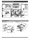
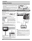
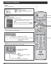
Connect the IR Blaster if you wish to send remote control signals
from the plasma TV to control the recording of a connected
video recorder.
Position the IR Blaster remote control emitter facing the signal
sensor of the video recorder and you will be able to easily record
programs from digital broadcasts using a video recorder
connected to the plasma TV.
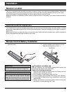
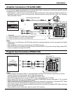
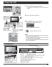
Setting the IR Blaster
IR Blaster Connection
Place the IR Blaster in front of the signal sensor of the video
recorder. (VCR)
Read the video recorder
operating instructions
regarding positioning of the
signal sensor.
If necessary, use the double sided adhesive tape (included)
to secure the IR Blaster to a flat surface.
e.g. Television stand surface
If you peel off the adhesive tape, the
surface may become damaged.
Once you have confirmed the video
recorder is operating correctly,
secure it by attaching the adhesive
tape.
DIGITAL
AUDIO OUT
G-LINK
IR Blaster (Supplied)
Infrared
emitter
Video recorder (VCR)
Video recorder
G-LINK jack
TV
TV
VCRDVD
DTV
RCVR
DBS/CBL
1 2 3
4 5 6
7 8
0
9
AUX
A
S
P
E
C
T
M
U
T
E
R
E
C
A
L
L
F
A
V
O
R
I
T
E
CH
VOL
CH
VOL
OK
+
-
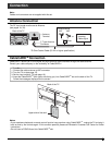
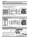
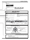
Introduction to recording scheduling using the IR
Blaster
You may do recording scheduling from the TV Guide of this
TV after installing the IR Blaster. (See page 43)
The TV acts as a proxy for some remote control
operations of the VCR.
Setting the recording time,
channel and recording
mode, etc.
Converts scheduling data
displayed on the TV to a
remote control signal and
sends it
Settings other than basic ones (such as recording time
and channel) must be set on the VCR.
TV
No need to set
recording time or
channel on the
video recorder
VCR
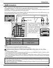
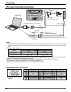
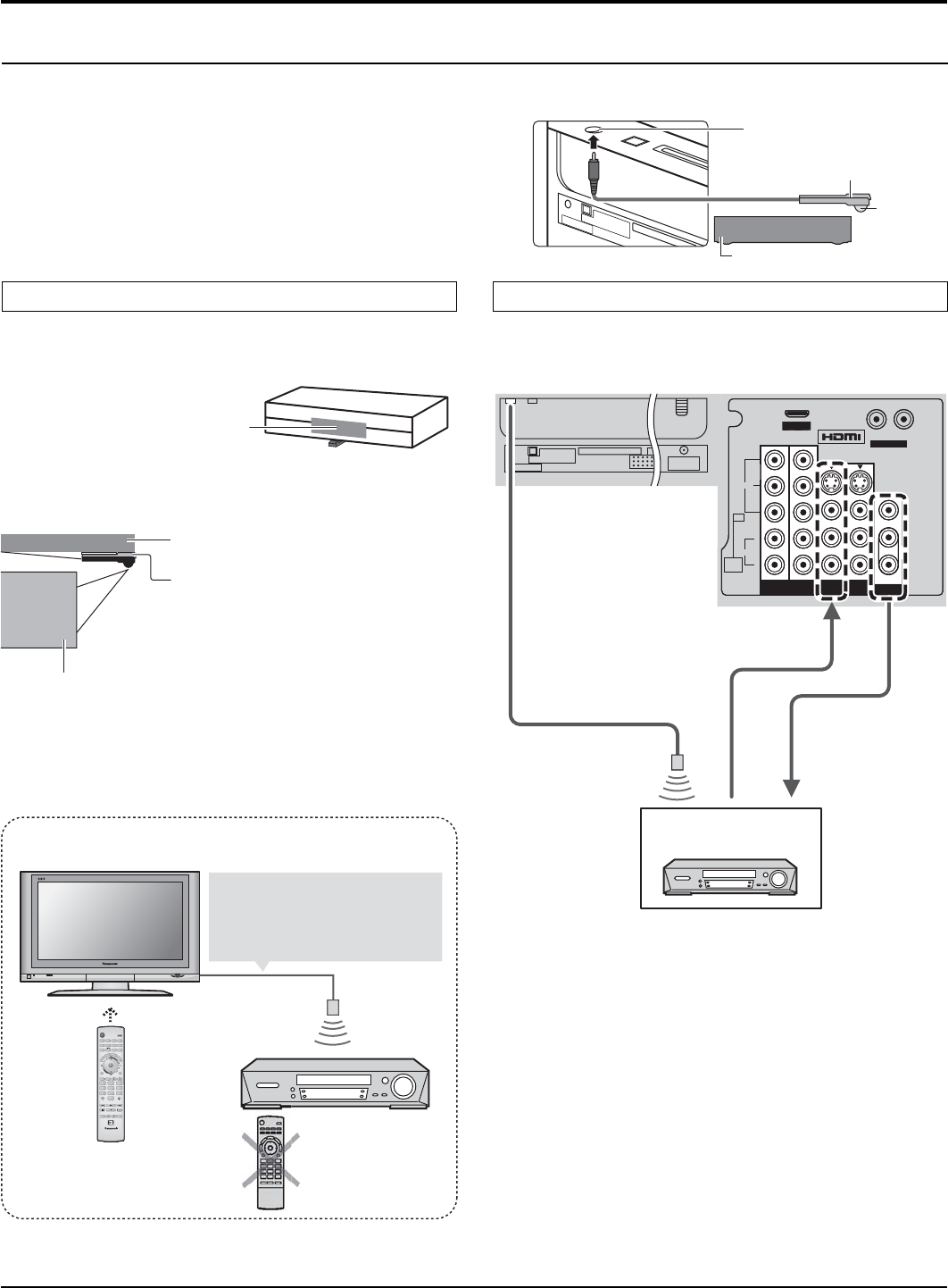
INPUT / OUTPUT Connection
With the IR Blaster connection setting timer recording can be done easily by using the TV GUIDE function in this set.
AV IN
R L
AUDIO IN
S VIDEO
VIDEO
L
R
Y
VIDEO
AUDIO
P
B
P
R
P
B
P
R
Y
PROGOUTCOMPONENT VIDEO
INPUT
1
2
INPUT 2 INPUT 1
TO AUDIO AMP
AUDIO
IN
PC
AV IN
R L
AUDIO IN
S VIDEO
VIDEO
L
R
VIDEO
AUDIO
P
B
P
R
P
B
P
R
Y
PROGOUTCOMPONENT VIDEO
INPUT
1
2
INPUT 2 INPUT 1
TO AUDIO AMP
AUDIO
IN
PC
ANTENNA
Cable In
DIGITAL
AUDIO OUT
G-LINK
Connection for recording to a VCR by using TV GUIDE
Back of the TVG-LINK
from
PROG.OUT
To INPUT 1
IR Blaster
VCR
Notes:
• The input signals connected to INPUT 1 cannot be output
from PROG. OUT terminals. (both Video and audio)
However, output can be obtained from optical Digital Audio
terminals.
(Input signals other than from INPUT 1 can be output
from PROG. OUT.)
• When you make schedule recording using TV Guide with
IR blaster, you have to select in your VCR Line-1 (L-1)
and set your VCR in OFF condition.
(Refer to the Operating Instruction manual of VCR)