


3
Objective...............................................................................................................5
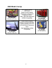
2002 Model Line Up..............................................................................................6
Specifications.....................................................................................................7
Features.............................................................................................................8
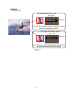
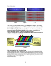
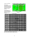
New Asymmetrical Cell Structure Panel .........................................................9
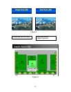
Model Differences...........................................................................................9
Disassembly .......................................................................................................11
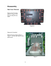
Rear Cover Removal .......................................................................................11
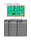
42” HD PCB Board Layout Diagram ...................................................................13
Printed Circuit Board Information Table ...........................................................13
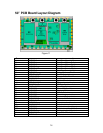
50” PCB Board Layout Diagram .........................................................................14
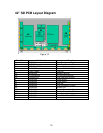
42” SD PCB Layout Diagram ..............................................................................15
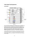
Video Signal Path Explanation............................................................................16
HY/HZ Board....................................................................................................16
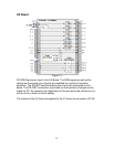
HX Board .........................................................................................................17
D1 Board..........................................................................................................18
DVI Interface....................................................................................................19
Sync Process...................................................................................................21
RGB/PC Input Mode Sync ...............................................................................21
Composite/ Component Video Input mode Sync .............................................21
D1 Board.............................................................................................................22
D1 Main ICs Operation ....................................................................................22
D2 Board.............................................................................................................23
D2 Board details ..............................................................................................24
SC Board Explanation.........................................................................................25
SS Board Explanation.........................................................................................28
Power Supplies...................................................................................................31
Standby Power Supply.....................................................................................31
Main Power Supply ..........................................................................................32
Power Factor Control....................................................................................32
Low Voltage Power supply............................................................................33
Voltage Regulation........................................................................................33
High Voltage Power Supply .............................................................................34
Protection Circuits...............................................................................................36
Diagnostic Procedures........................................................................................38
Self Check Display Indication...........................................................................38
Power LED Flashing timing chart.....................................................................39
Diagnostic Flow Charts .......................................................................................40
No Power .........................................................................................................40
The Power LED is red and blinking on/off........................................................41
Power LED blinks twice ...................................................................................42
No Picture Flowchart 1.....................................................................................43
No picture Flowchart 2 .....................................................................................44
Dark picture Flowchart .....................................................................................45
Local screen failure.............................................................................................46