


26
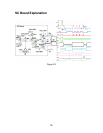
Figure 24
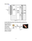
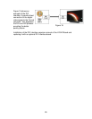
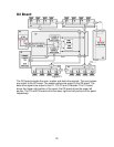
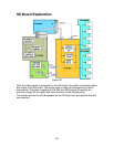
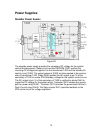
The SC Board consists of buffers and drivers used to generate the scan signals
to the panel. The buffers provide isolation between the D2 board and the drivers.
Connector SC20 provides the drive signals (140V, 100V and 18V). Connector
SC21 provides trigger signals to switch the FET transistors. The D2 board
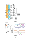
switches the FETs on and off to create the distinctive scan signal. Each trigger
signal switches a drive FET creating a portion of the waveform. For example,
applying the CPH signal to the 140V FET creates the peak portion of the
waveform, see figure 23.