


21
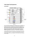
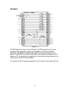
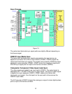
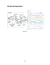
Sync Process
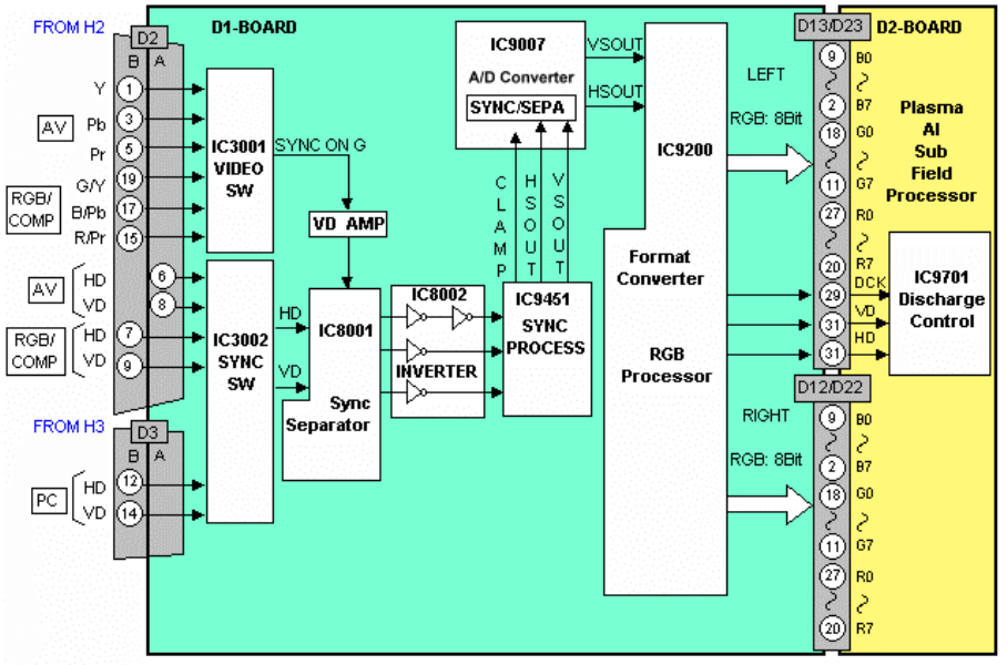
Figure 19
The vertical and horizontal sync signal paths are slightly different depending on
the Source signal.
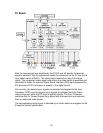
RGB/PC Input Mode Sync
The vertical and horizontal sync signals generated by the input device are
applied to connector D3 or D2 to a Sync switch (IC3002). IC3002 outputs the
vertical and horizontal sync signals. The signals are inverted by IC8002 and then
applied to a sync processor (IC9451). IC9451 mixes the image sync signal with
the OSD sync signal prior to output to the format converter (IC9200).
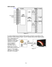
Composite/ Component Video Input mode Sync
The video signals are applied to an input switch (IC3001). The output signal is
separated into Y, Pb and Pr with Sync on green signal. The Sync on green signal
is applied to a sync separator (IC8001). IC8001 outputs the Vertical and
Horizontal sync signals. From that point on the sync path is the same as the
RGB/PC input mode.
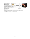
The A/D converter (IC9007) shapes the analog sync signal to clean digital pulses
prior to input to the format converter.