


22
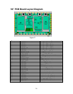
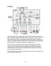
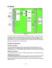
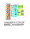
D1 Board
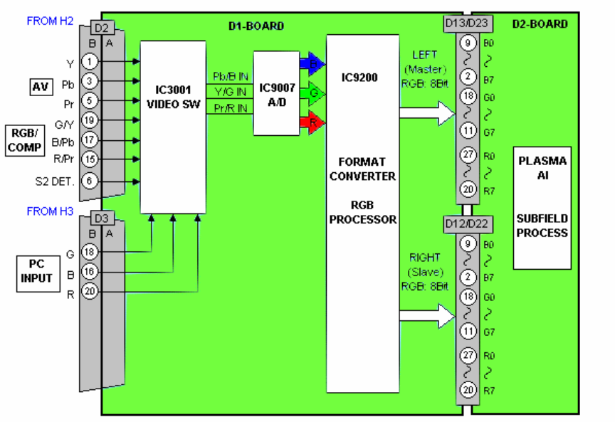
Figure 20
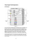
D1-board consists of the Analog and Digital signal process. It also contains the
Discharge control and Microprocessor control block. Supply voltages of 13.5V,
5V, Standby 5V, 3.3V, and 1.8 V operate the D1-board. The input RGB video
signals are at 0.7Vp-p. Video signals in the form of parallel data and the control
signals for the data drive circuit are output.
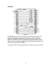
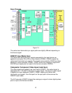
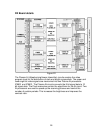
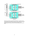
D1 Main ICs Operation
IC3001 Video Switch
The user selects the desired video input using the front panel button or the
remote control. The microprocessor reads this data and sends out a command
via the IIC bus line. The IIC data is read by IC3001 and the video input is chosen.
IC9007 A/D Converter
This integrated circuit converts the RGB analog signals to eight bit parallel data.
IC9200 Format Converter
The digital video data is converted to progressive scan and mixed with the OSD
data. Other adjustments such as white balance, contrast and color are also
corrected here. The two channels of data are output to the D2 board for the sub-
field drive circuit.