


27
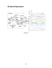
Figure 25
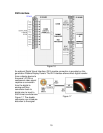
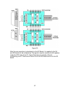
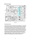
After the scan waveform is developed on the SC Board, it is applied to the SU
and SD boards for de-multiplexing. The signal is input to a series of shift registers
inside the PDP scan driver IC. Figure 25 shows an example of the de-
multiplexing circuit. There are six driver ICs on the SU board and six on the SD
board.