


- 11 -
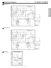
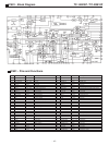
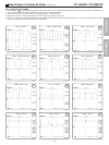
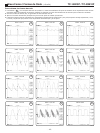
TC-14B10P / TC-20B10PService Adjustments and Calibrations
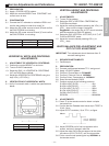
VERTICAL HEIGHT AND CENTERING
ADJUSTMENTS
1- ADJUSTMENTS.
1.1- Tune a Philips pattern.
1.2- Select the DAC of VERTICAL CENTERING at
CHQ3 Service Mode.
1.3- Adjust the vertical placement pressing the VOL(+) or
VOL(
_
) keys until the image is centered.
Suggestion: the center line of CRT should coincide
with the centerline of PHILIPS pattern).
1.4- Select the DAC VERTICAL ALTITUDE (V ALT) AT
CHQ3 at SERVICE mode.
1.5- Adjust the correct altitude pressing VOL(+) or
VOL(
_
) keys
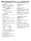
WHITE BALANCE PRE ADJUSTMENT AND
CRT CUT OFF ADJUSTMENT
IMPORTANT: This adjustment should be done after 15
minutes heating time.
1- REQUIRED INSTRUMENTS
1.1- Oscilloscope
2- PREPARATION.
2.1- Connect oscilloscope between TPY1 and ground.
2.2- Apply a PHILIPS pattern.
2.3- Confirm if Picture Menu is DYNAMIC
2.4- Confirm if Channel Color is NORMAL
2.5- Confirm Colour Temperature in NORMAL
2.6- Enter Service Mode at CHQ5.
2.7- Position controls at the following positions:
R HIGH LIGHT(R-DR).........40H
B HIGH LIGHT(B-DR).........4OH
R LOW LIGHT (R-CUT)..........000H
B LOW LIGHT(B-CUT)........000H
GLOW LIGHT(G-CUT)........125H
SCREEN........MINIMUM
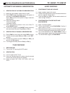
3- ADJUSTMENTS
3.1- Press 5 at the remote control to obtain a simple
horizontal line.
3.2- Confirm that the Pedestal level value at pin TPE27 is
2,2±0,1Vp-p.
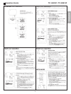
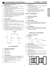
3.3- Adjust G-CUT to obtain (*A) at TPY1, as figure
below:
3.4- Adjust SCREEN until a first line appears at the
screen, and dont change it after this.
3.5- Adjust the other DACs that correspond to the other
two colours (R-CUT,B-CUT) until line turns white.
3.6- Exit to normal mode pressing the key NORMAL at
the remote control.
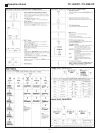
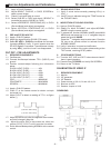
DIÂMETRO A MODELO
20 polegadas290 ± 5 mm
14 polegadas200 ± 5 mm
(*A) 14 140±2Vp-p
(*A) 20 160±2Vp-p
0 V
2- PREPARATION
2.1- Apply a CROSS HATCH pattern.
2.2- Adjust the controls BRIGHT and CONTRAST until
current turns to zero.
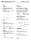
3- CONFIRMATION
3.1- Connect the DC voltmeter to cathode of D591 and
confirm that voltage is lower than level(*)A.
3.2- Adjust the DC power source to level(*)B and confirm
that SHUTDOWN is not acting.
3.3- Adjust the DC power source to level(*)C and confirm
that SHUTDOWN is not acting.
HORIZONTAL WIDTH AND CENTERING
ADJUSTMENTS
1- ADJUSTMENT OF HORIZONTAL CENTERING
1.1- Position the control BRIGHT to minimum.
1.2- Tune to PHILIPS standards.
1.3- Select the DAC of HORIZONTAL CENTERING
(HC) at CHQ3 Service Mode.
1.4- Adjust the HORIZONTAL CENTERING using the
keys VOL(+) OR VOL(-).
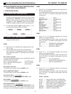
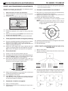
2- VERIFICATION OF HORIZONTAL WIDTH
2.1- Verify if horizontal width, is within the specifications
below:
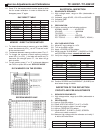
LEVELS 14 (V) 20 (V)
21,60 22,30
(
*
)B
23,60 24,10
(
*
)C
25,60 26,10
(
*
)A
ENGLISH