


- 2 -
General Guidelines
An Isolation Transformer should always be used during the servicing of a
receiver whose chassis is not isolated from the AC power line. Use a
transformer of adequate power rating as this protects the technician from
accidents resulting in personal injury from electrical shocks. It will also
protect the Receiver from being damaged by accidental shorting that may
occur during servicing.
When servicing, observe the original lead dress, especially in the high
voltage circuit. Replace all damaged parts (also parts that show signs of
overheating.)
Always Replace Protective Devices, such as fishpaper, isolation resistors
and capacitors, and shields after servicing the Receiver. Use only
manufacturers recommended rating for fuses, circuit breakers, etc.
High potentials are present when this Receiver is operating. Operation of
the Receiver without the rear cover introduces danger from electrical
shock. Servicing should not be performed by anyone who is not thoroughly
familiar with the necessary precautions when servicing high-voltage
equipment.
Extreme care should be practiced when Handling the Picture Tube. Rough
handling may cause it to implode due to atmospheric pressure (14.7 lbs
per sq. in). Do not sick or scratch the glass or subject it to any undue
pressure. When handling, use safety goggles and heavy gloves for
protection. Discharge the picture tube by shorting the anode to chassis
ground (not to the cabinet or to other mounting hardware). When
discharging, connect cold ground (i.e. dag ground lead) to the anode
with a well insulated wire or use a grounding probe.
Avoid prolonged exposure at close range to unshielded areas of the picture
tube to prevent exposure to X-ray radiation.
The Test Picture Tube used for servicing the chassis at the bench should
incorporate safety glass and magnetic shielding. The safety glass provides
shieldinf for the tube viewing area against X-ray radiation as well as
implosion. The magnetic shield limits X-ray radiation around the bell of
the picture tube in addition to restricting magnetic effects. When using a
picture tube test jig for service, ensure that the jig is capable of handling
31kV without causing X-ray radiation.
Before returning a serviced receiver to the owner, the service technician
must thoroughly test the unit to ensure that is completely safe to operatore.
Do not use a line isolation transformer when testing.
Important Safety Notice
Special components are used in this television set which are important for safety. These parts are identified on the schematic
diagram by the symbol . It is essential that these critical parts are replaced whit the manufacturers specified replacement
parts to prevent X-ray radiation, shock, fire or other hazards. Do not modify the original design whitout manufacturers permission.
WARNING !!
Esquema Elétrico do chassi MX5Y ................. (em anexo)
Conserve-o sempre junto deste manual.
TABLE OF CONTENTS
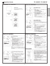
OPERATION GUIDE ............................................................................. 03
SERVICE ADJUSTMENTS AND CALIBRATIONS
HOW TO OPERATE THE DAC CONTROLS ..................................... 06
HOW TO ENTER THE SERVICEMAN MODE ..................................... 06
HOW TO EXIT THE SERVICEMAN MODE ......................................... 06
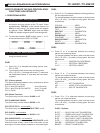
DAC DIRECT TABLE ............................................................................ 07
MEMORY - DIRECT ACCESS METHOD ............................................. 07
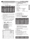
EEPROM - MEMORY MAP .................................................................. 07
ELECTRICAL INSPECTION .................................................................. 07
INSPECTION OF THE DEFLECTION CIRCUITS ................................ 07
CUT OFF - PRE ADJUSTMENTS ........................................................ 08
CALIBRATION OF VIDEO IF ................................................................ 08
AFT ADJUSTMENTS ............................................................................. 09
AGC-RF ADJUSTMENTS ...................................................................... 09
NOISE LEVEL ADJUSTMENTS ............................................................ 09
VIDEO OUT ADJUSTMENTS ............................................................... 10
SUB-CONTRAST ADJUSTMENTS ....................................................... 10
COLOUR SATURATION ADJUSTMENTS .......................................... 10
SHARPNESS ADJUSTMENTS ............................................................. 10
SHUT DOWN SYSTEM COFIRMATION .............................................. 10
HORIZONTAL WIDTH AND CENTERING ADJUSTMENTS .............. 11
VERTICAL HEIGHT AND CENTERING ADJUSTMENTS ................... 11
WHITE BALANCE PRE ADJUSTMENTS ........................................... 11
CRT CUT OFF ADJUSTMENTS ........................................................... 11
FOCUS ADJUSTMENTS ..................................................................... 12
FRONT PANEL CHECKING ................................................................. 12
AV IN TERMINALS CHECKING ........................................................... 12
AUTOMATIC AND MANUAL MEMORIZATION .................................... 13
TUNE CHECKING ................................................................................. 13
AUDIO CHECKING ................................................................................ 13
PURITY AND CONVERGENCE ADJUSTMENTS .............................. 14
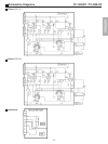
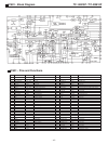
SCHEMATICS DIAGRAMS ................................................................... 15
IC601 BLOCK DIAGRAM / PINS AND FUNCTIONS ........................... 16
WAVE FORMS ...................................................................................... 17
CABINET PARTS LOCATION ............................................................... 19
CABINET REPLACEMENT PARTS LIST ............................................. 20
ELECTRICAL REPLACEMENT PARTS LIST ...................................... 21
Warning !
It is essential that these critical parts are replaced
with the manufacturers specified replacement parts
to prevent X-ray radiation, shock, fire or other
hazards.
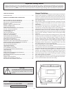
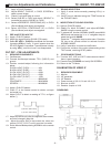
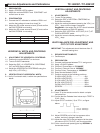
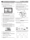
HOW TO OPEN THE CABINET
Screw
Screw