


- 9 -
TC-14B10P / TC-20B10PService Adjustments and Calibrations
3- ADJUSTMENTS
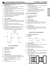
3.1- Adjust AFT using coil L167 until the voltage below
(*) is obtained at TPE29.
(*) 4,0±1,0V (after 10 seconds ON)
(*) 4.5±1,0V (after heating)
3.2- Vary the frequency of CW oscillator between
±100KHz and verify if tension variation at the
multimeter is higher than ±1,2V
AGC-RF ADJUSTMENTS
1- REQUIRED EQUIPMENT
1.1- Digital Multimeter
1.2- Attenuator
2- PREPARATION
2.1- Tune a COLORBAR patten.
2.2- Adjust the input signal level to 64±2dB ( 75Ω open).
2.3- Connect Digital multimeter between TPE23 and
ground
3- ADJUSTMENTS
3.1- Select DAC AGC RF(RF) CHQ4 (Service Mode)
3.2- Adjust the DAC using the keys VOL(+) and VOL(
_
)
until ±6,2V at TPE23.
NOISE LEVEL ADJUSTMENTS
1- REQUIRED EQUIPMENTS
1.1- Oscilloscope
1.2- 7KHz filter
2- PREPARATION
2.1- Tune a COLORBAR patten (no sound modulation).
2.2- Position tone control to center
2.3- Position VOLUME control to maximum.
2.4- Connect Oscilloscope to speakers terminals.
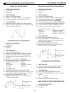
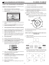
3- VERIFICATION
3.1- The maximum amplitude of the noise signal should
be less than 1,5Vp-p.
3.2- When it is higher than 1,5Vp-p, activate 7KHz filter
at the speakers terminals and verify if noise level is
less than 0,5Vp-p.
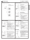
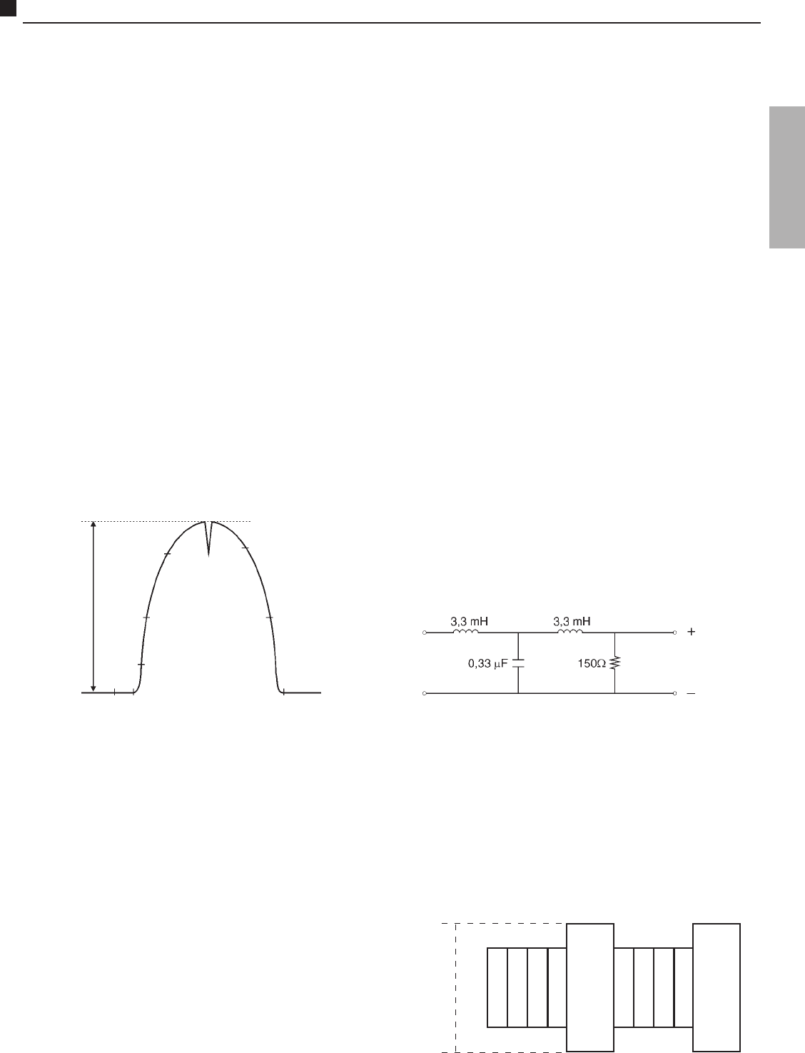
Oscilloscope
1,5Vp-p
CALIBRATION OF VIDEO IF ( continuing)
1- PREPARATION
2.1- Connect the VIF generator positive output cable to
TPE33 and the negative to ground.
2.2- Connect the VIF detector positive output cable to TPE13
and negative to ground.
2.3- Connect the +9V power source positive to pin 3 of IC851
and negative to ground.
2.4- Connect the +4V power source positive in series with
1KΩ resistor to pin 63 of IC601 and negative to ground.
2.5- Connect the polarization of AGC with positive to TPE21
(IF AGC) and negative to the ground.
2.6- Enter Serviceman Mode.
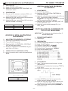
2- ADJUSTMENTS
3.1- Calibrate monitor to 200mVp-p
3.2- Decrease the VIF generator output to minimum signal.
3.3- First, turn on the instruments and after that, the power
sources.
3.4- Adjust bias AGC to obtain maximum gain.
3.5- Adjust the VIF generator output to obtain 200mVp-p at
the monitor.
3.6- Increase 20dB to VIF generator output and adjust the
Bias AGC to obtain 200mVp-p at the monitor
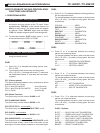
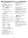
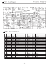
3.7- Confirm that the level of CC (42,17 MHz) and PC (
45,75 MHz) are within the especificated below.
AFT ADJUSTMENTS
1- REQUIRED EQUIPMENTS
1.1- Oscilator CW 45,75 MHz
1.2- VIF detector
1.3- Digital multimeter
1.4- Short Jumper
2- PREPARATION
2.1- Disconnect the signal from the antenna terminal
2.2- Connect the multimeter between TPE29 and ground
2.3- Connect the CW oscilator using VIF detector
between TPE33 and ground
2.4- Adjust the CW oscilator output to 90+-5dBu
(75Ω open).
2.5- Position the DAC AFT in 80H.
200m Vp-p
39,75
41,25
47,25
41,65
CC 42,17
45 ± 15%
PC 45,75
45 ± 15%
42,75
45,00
ZERO BEAT
↓
ENGLISH