19
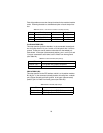
SGND & FRGND (JB4)
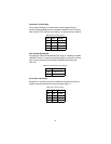
In the connected (closed) position, this strap links DB-25 pin 7 (Signal
Ground) and frame ground. In the open (disconnected) position, pin 1 is
“lifted” from frame ground (see Table 22).
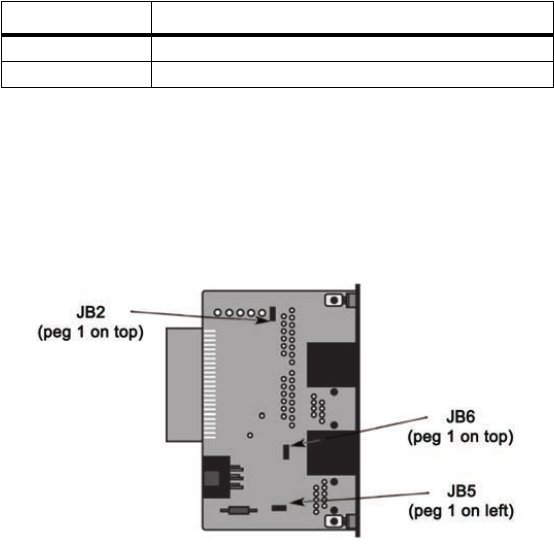
RJ-45/RJ-11 & RJ-45/RJ-45 Strap Settings
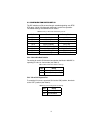
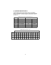
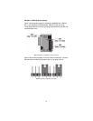
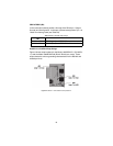
Figure 6 shows strap locations for the Model 1000RCM1D11 (RJ-45/RJ-
11) and the Model 1000RCM1D45 (RJ-45/ RJ-45) rear cards. These
straps determine various grounding characteristics for the RS-232 and
twisted pair lines.
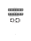
Figure 6.
RJ-45/RJ-11 & RJ-45/RJ-45 strap locations
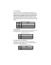
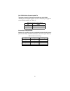
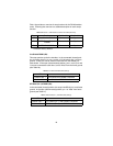
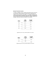
Table 22:
SGND & FRGND (JB4) Settings
JB4
Position 1&2 = SGND (pin 7) and FRGND Connected
Position 2&3 = SGND (Pin 7) and FRGND Not Connected


