8
3.0 CONFIGURATION
This section describes the location and orientation of the Model
1080ARC’s configuration switches and provides detailed instructions on
setting each of the switches.
The Model 1080ARC uses a unique package of 24 DIP switches that
allow configuration to an extremely wide range of applications. These 24
DIP switches are accessible when the card is slid out of the rack chassis.
Once configured, the Model 1080ARC is designed to operate transpar-
ently, without need for frequent re-configuration.
3.1 SWITCH LOCATIONS AND ORIENTATION
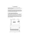
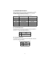
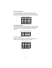
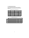
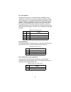
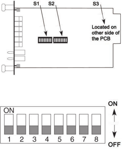
The Model 1080ARC has three sets of eight switches—S1, S2, and S3—
which are mounted on the PC board (Figure 1). These configuration
switches allow you to select data rates, clocking methods, V.52 & V.54
tests, word lengths, extended signaling rates, async. or sync. mode, 2- or
4-wire operation, antistream control and input impedance. As Figure 2
shows, the orientation of all DIP switches is the same with respect to
“ON” and “OFF” positions.
Figure 1.
Model 1080ARC board, showing location of DIP switches
Figure 2.
Close-up of DIP switches showing “ON” and “OFF” positions


