Pelco Manual C682M-E (11/01) 7
INSTALLATION
Place the DVR on any flat surface (desk or table) or install in any standard 19-inch (48.26 cm)
wide console or rack configuration.
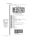
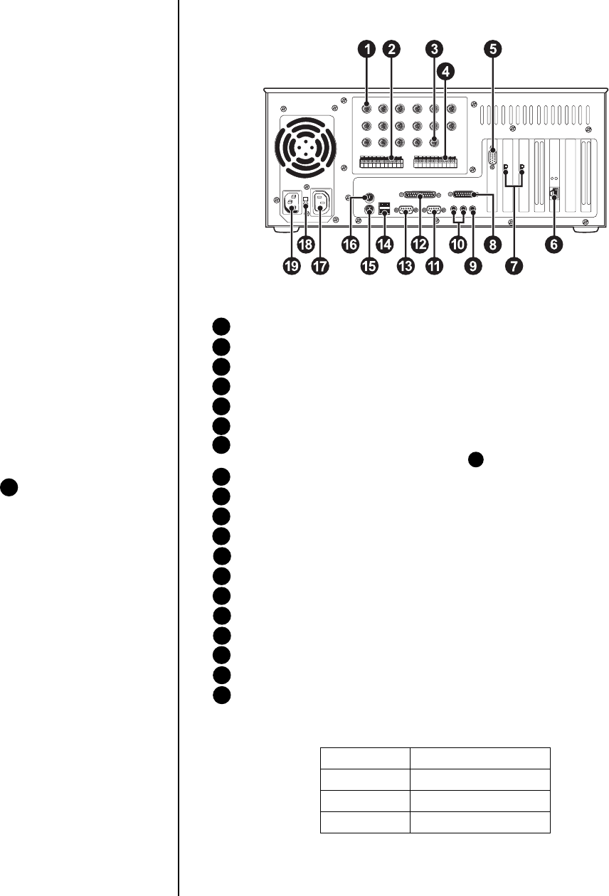
Figure 1. Rear View of Back Panel
1 Camera Inputs – Refer to Table A for video coaxial cable distances.
2 Alarm Inputs
3 Analog Monitor Output
4 Relay Outputs
5 PC Monitor Output
6 LAN Port (Internet or TCP/IP)
7 NTSC/PAL Selection Switches – Setting must correspond with the software
setup for NTSC/PAL. Refer to Figure 6, item 2 .
8 Joystick Port (Not used)
9 Microphone Jack (Not used)
10 Audio IN/OUT (Not used)
11 COM 2 Serial Port – Connection for optional external modem.
12 Printer Port
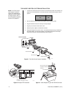
13 COM 1 Serial Port – RS-422 two-wire control output; refer to Figure 2.
14 USB Connection – For optional USB device (CD-RW).
15 Keyboard (PS/2)
16 Mouse (PS/2)
17 AC Power Output
18 115/230 VAC Power Switch
19 AC Power Input
Table A. Video Coaxial Cable Requirements
Cable Type* Maximum Distance
RG59/U 750 ft (229 m)
RG6/U 1,000 ft (305 m)
RG11/U 1,500 ft (457 m)
* Minimum cable requirements:
75 ohms impedance
All-copper center conductor
All-copper braided shield with 95% braid coverage
00589
NOTE:
Set the PAL/NTSC
Switch to the proper setting
for your application. Refer to
7
.
NOTE:
An UPS (Uninter-
rupted Power Supply) is not
supplied with the DVR.
If required, Pelco recom-
mends a device with the
following specifications:
Capacity –
350 VA, 210 watts
Output voltage –
115 V
±
8% (on battery)
Frequency range –
47 Hz to 63 Hz


