


20 Connect Peripheral equipment
Connect Peripheral equipment
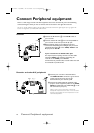
There is a wide range of audio and video equipment that can be connected to your TV.The following
connection diagrams show you how to connect them to the back or the right side of the TV.
AV1
IN can handle CVBS and YPbPr; AV2
IN CVBS and Y/C;AV3 and AV4
IN
digital signals of a e.g. digital HD
receiver or Progressive scan DVD; SIDE: CVBS and Y/C.
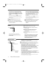
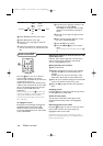
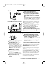
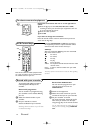
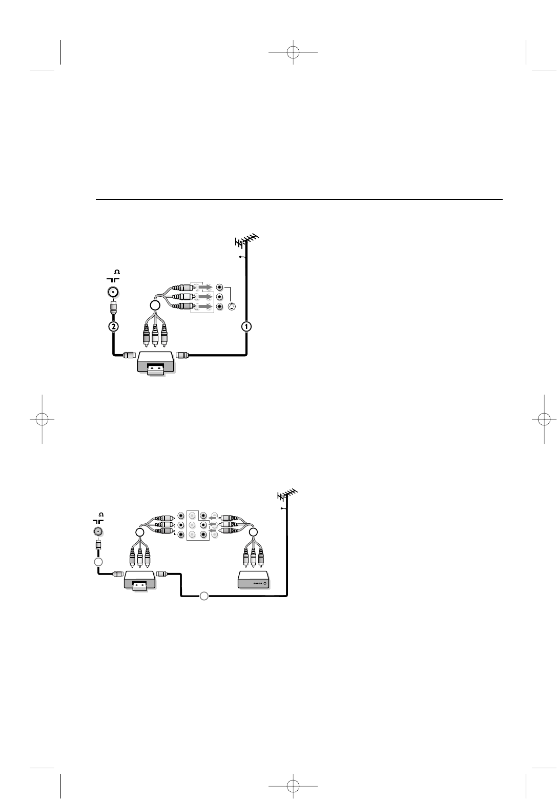
&Connect the RF Antenna 1 to the RF IN socket of
your recorder.
éConnect another RF cable 2 from the output
OUT of
your recorder to the TV’s input 75 ø x jack.
“Better playback quality can be obtained if you also
connect the Video,Audio Left and Right (only for stereo
equipment) AV cables 3 to the
VIDEO, AUDIO L and
R input jacks of AV2 IN.
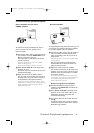
If your recorder has an S-VHS video jack:
For improved picture quality, connect an S-video cable
with the
S-VIDEO input instead of connecting the
recorder to the
VIDEO jack of AV2 IN.
S-Video does not provide audio, so audio cables must still
be connected to provide sound.
CABLE
REC
75
OUT
OUT IN
AV 2
in
AV 1
in
Monitor
out
VIDEO
L/Mono
R
Y
Pb
Pr
AUDIO
S-VIDEO
3
Recorder
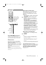
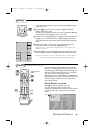
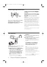
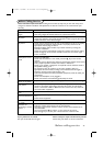
& Connect your recorder as described above.
The
MONITOR OUT connectors can be used to
record programmes from your TV 4.
See Record with your recorder, p. 24.
é Connect the Video,Audio left and Audio right
(only for stereo equipment) cables to the
VIDEO,
AUDIO L and R input jacks of AV1 IN 5 or the
side connections (see p. 21).
Note: In case of mono equipment, only the left
loudspeaker reproduces sound. Use a mono to stereo
adaptor (not supplied) for sound reproduction via all
internal loudspeakers.
Recorder and other A/V peripherals
75
CABLE
REC
AV 2
in
AV 1
in
Monitor
out
L/ Mono
R
Y
Pb
Pr
AUDIO
S-VIDEO
IN
OUT
OUT IN
TV
x
1
2
5
S-VIDEO
4
315 2163.1 (16X24) 22-10-2002 13:15 Pagina 20