


21Connect Peripheral equipment
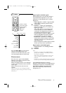
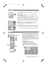
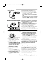
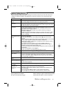
Satellite Receiver
& Connect the satellite antenna cable 1 to the
satellite receiver’s
SATELLITE IN jack.
é Connect the Video,Audio left and right (only for
stereo equipment),AV cables 2 to the
VIDEO, L
and R AUDIO input AV1 IN jacks.
If your satellite receiver has an S-VHS video
jack:
For improved picture quality, connect an S-VHS video
cable with the
S-VIDEO input instead of connecting
the satellite receiver to the
VIDEO jack of AV2 IN.
SAT
≈
SAT
IN
Monitor
out
Y
Pb
Pr
VIDEO
L/ Mono
R
AUDIO
S-VIDEO
AV 2
in
AV 1
in
OUT
2
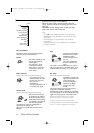
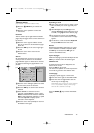
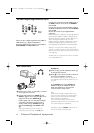
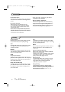
Satellite Receiver with a recorder
& Connect your satellite receiver as described above.
é Connect the RF Antenna or Cable TV cable 1 to
the
RF IN socket of your recorder.
“ Connect another RF cable 2 from the output of
your recorder to the TV’s 75 ø x jack.
‘ Connect the satellite antenna cable 3 to the
satellite receiver’s
SATELLITE IN jack.
( Connect the AV cables 4 to the satellite receiver’s
AV OUT jacks and to the VCR’s AV IN jacks.
§ Connect the recorder’s
AV OUT jacks 5 to the TV’s
AV2 IN jacks.
REC
CABLE
SAT
≈
IN OUT
SAT
IN
OUT
IN
OUT
AV 2
in
AV 1
in
Monitor
out
VIDEO
L/Mono
R
Y
Pb
Pr
AUDIO
S-VIDEO
5
75
3
4
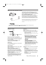
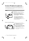
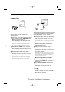
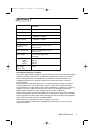
DVD player or other accessory digital source equipment
Equipment with AV connectors only
& Connect the video cables to the
equipment’s
AV OUT jacks and to the
TV’s
AV1 or AV2 IN jacks.
é Connect the audio cables to the
equipment’s
AUDIO L and R jacks and to
the
L AUDIO and R AUDIO AV1 or AV2
jacks on the TV. (According to where you
connected the video cables, to
AV1 or
AV2.)
Equipment with an S-VIDEO
connector
& Connect an S-video cable the
AV2
S-VIDEO input.
Note:When using the
S-VIDEO connector
do not connect any device to the video input.
é Connect the audio cables to the
equipment’s
AUDIO L and R jacks and to
the
L AUDIO and R AUDIO AV2 jacks
on the TV.
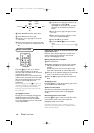
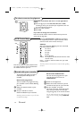
With Component Video Output Connectors
& Connect the cables of your YPbPr equipment to
the
YPbPr input AV1 IN sockets on the TV.
Note:When using the YPbPr sockets do not connect any
device to the video input of AV1.
Note:The YPbPr sockets on the TV are compatible with
480i (interlaced, 1 Fh) output signals only, not 480p
(progressive scan, 2 Fh).
é Connect the Audio left and right (only for stereo
devices) cables to the
AUDIO L and R input of AV1.
Warning: Never connect a signal to the Y-input and
video-input at the same time.This may cause
picture distortion !
Equipment with Progressive scan output (480p or
1080i 2 Fh)
Connect the equipment to the AV3 or AV4 IN jacks on
the TV. See
AV3 or AV4 Digital HD input, next page.
Note:The labels for the component video sockets may differ
depending on the DVD player.Although the abbreviations
may vary, the letters B and R stand for the blue and red
component signals, respectively, and Y indicates the
luminance signal. Refer to the DVD player’s instructions for
use for definitions and connection details.
AV 2
in
AV 1
in
Monitor
out
VIDEO
L
R
Y
Pb
Pr
AUDIO
S-VIDEO
315 2163.1 (16X24) 22-10-2002 13:15 Pagina 21