


6
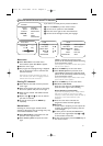
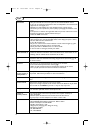
Recorder (VCR-DVD+RW)
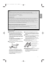
Note: Do not place your recorder too close to the screen as some recorders may be susceptible for signals from the
display. Keep a minimum distance of 20” from the screen.
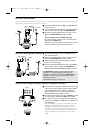
Recorder and other A/V devices
AV2 MON.OUT
VIDEO/AUDIO VIDEO/AUDIO
S-VIDEO
R
x ANTENNA
CABLE
RECORDER
IN OUT
4
3
AV2 MON.OUT
VIDEO/AUDIO VIDEO/AUDIO
x ANTENNA
S-VIDEO
R
RECORDER
CABLE
3
4
OUT IN
x
TV
& Connect the RF Antenna cable 1 to the RF IN socket
of your recorder.
é Connect another RF cable 2 from the output OUT of
your recorder to the TV’s input x
ANTENNA jack.
“ Connect the supplied adaptor cable mini-jack to cinch
3 to the
VIDEO/AUDIO input jack of AV2.
If your recorder has an S-VHS video jack:
For improved picture quality, connect an S-video cable
4 with the
S-VIDEO input.
S-VHS does not provide audio, so the mini-jack to cinch
cable must still be connected to provide sound.
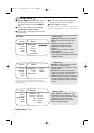
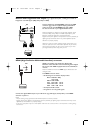
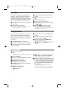
Devices with Component Video Output Connectors (YPbPr)
& Connect the three separate component video cables 1
to the device having component video outputs (YPbPr),
such as DVD-players, laser-disc players, videogame
players, satellite receivers,or other equipment and to
the
Y, Pb and Pr jacks of AV1 on the TV.
é Connect the audio cable to the device’sAUDIO L and R
jacks and to the L and R audio YPbPr jacks of AV1.
“ For reproduction of CVI (Component Video Input) also
connect to the
CVBS jack of AV1. See the handbook of
your DVD player.
Note: the labels for the component video sockets may differ
depending on the DVD player or the device connected.
Although the abbreviations may vary the letters B and R
stand for blue and red component signals, respectively, and Y
indicates the luminance signal. Refer to the DVD player’s or
device’s instructions for use for definitions and connection
details.
AV1 (1Fh)
Pr
AUDIO
Pb Y
RLCVBS
VIDEO
L/Mono
AUDIO
1
VIDEO
L/Mono
AUDIO
DVD
2
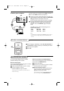
& Connect the RF Antenna 1 to the RF IN socket of
your other A/V device.
é Connect the supplied adaptor cable mini-jack to cinch
2 to the
VIDEO/AUDIO input jack of AV2.
“ Connect the RF output of the A/V device to the RF
input on the recorder 3.
‘ Connect another RF cable 4 from the output OUT of
your recorder to the TV’s input x
ANTENNA jack.
If your recorder has an S-VHS video jack, see above.
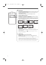
The
MON.OUT
connector can be used for a daisy
chaining or to record programmes from your TV.
Only when a recorder is connected to
MON.OUT
it is
possible to record a programme from other devices
connected to the TV.
See Record with your recorder, p. 13.
2375.1 en 16-07-2004 16:07 Pagina 6