


31
CONNECTING PERIPHERAL EQUIPMENT
VIDEO
Pb
Pr
VIDEO
S-VIDEO
L
AUDIO
L
R
AUDIO
L
R
G/Y
R/Pr
B/Pb
V
H
SYNC
L
R
AUDIO
L
R
AUDIO
AV4-480p/1080i-60Hz, 576p-50Hz
AV5-RGB, 480p/1080i-60Hz, 576p-50Hz
INPUT-AV 2 SUBWOOFERMONITOR
OUT
INPUT-AV 1
Y
REAR OF TV
ANTENNA IN 75Ω
L
REAR OF TV
4
1
VIDEO RECORDER
CABLE
A/V IN A/V OUT
3
RF OUT RF IN
2
5
A/V PERIPHERAL
RF INRF OUT
VIDEO
S-VIDEO
L
Pb
Pr
VIDEO
S-VIDEO
L
AUDIO
L
R
AUDIO
L
R
G/Y
R/Pr
B/Pb
V
H
SYNC
L
R
AUDIO
L
R
AUDIO
AV4-480p/1080i-60Hz, 576p-50Hz
AV5-RGB, 480p/1080i-60Hz, 576p-50Hz
INPUT-AV 2 SUBWOOFERMONITOR
OUT
INPUT-AV 1
Y
VIDEO
Pb
Pr
VIDEO
S-VIDEO
L
AUDIO
L
R
AUDIO
L
R
G/Y
R/Pr
B/Pb
V
H
SYNC
L
R
AUDIO
L
R
AUDIO
AV4-480p/1080i-60Hz, 576p-50Hz
AV5-RGB, 480p/1080i-60Hz, 576p-50Hz
INPUT-AV 2 SUBWOOFERMONITOR
OUT
INPUT-AV 1
Y
ANTENNA IN 75Ω
VIDEO
Pb
Pr
VIDEO
S-VIDEO
L
AUDIO
L
R
AUDIO
L
R
G/Y
R/Pr
B/Pb
V
H
SYNC
L
R
AUDIO
L
R
AUDIO
AV4-480p/1080i-60Hz, 576p-50Hz
AV5-RGB, 480p/1080i-60Hz, 576p-50Hz
INPUT-AV 2 SUBWOOFERMONITOR
OUT
INPUT-AV 1
Y
ANTENNA IN 75Ω
2
1
DVD PLAYER
COMPONENT VIDEO
OUT
A/V OUT
REAR OF TV
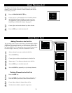
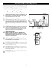
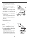
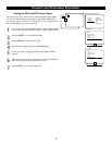
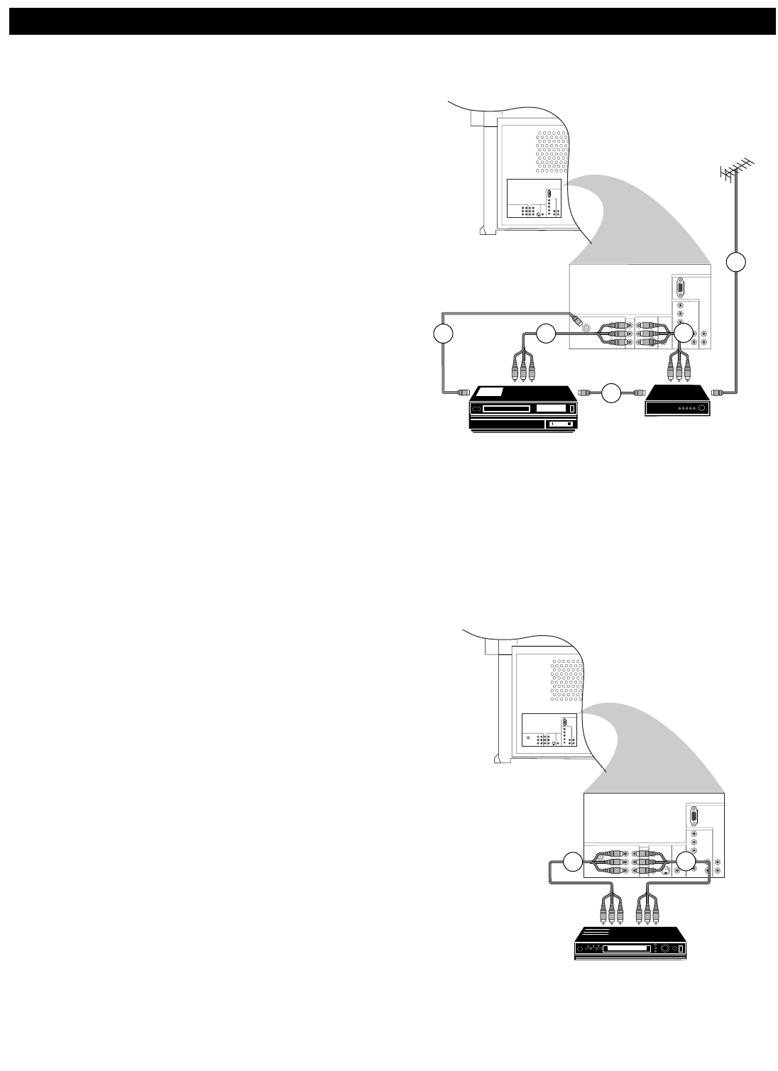
Video Recorder and Other A/V Peripherals
1
Connect the RF cable to the RF socket on your A/V peripheral
equipment.
2
To obtain better picture quality, also connect the Video and
Audio left and Audio right (only for stereo equipment) cables to
the VIDEO and AUDIO L (mono) and AUDIO R input of the
INPUT-AV 2 sockets.
Note :
In case of mono equipment, only the left loudspeaker
reproduces sound. Use a mono-to-stereo adaptor (not supplied)
for sound reproduction via the internal loudspeakers.
3
Connect the RF output of the A/V peripheral equipment to the
RF input on the video recorder.
4
When a video recorder is not connected to MONITOR OUT
on your TV, you can record a programme only from the aerial
or from the cable system.
Only when a video recorder is connected to MONITOR OUT
is it possible to record a programme from other equipment con-
nected to the TV. See page 32.
Connect Video and Audio left (mono) and Audio right cables
from the video recorder A/V inputs to the VIDEO and
AUDIO L (mono) and AUDIO R sockets of the MONITOR
OUT on your TV.
5
Connect from the RF output on the video recorder to the
ANTENNA IN 75Ω socket on your TV.
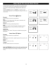
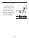
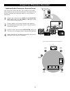
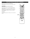
DVD Player
Note : Progressive-scan DVD players can be connected to the AV 4 or
AV 5 inputs only.
1
Connect the cables of your DVD player with component video
output to the Y-Pb-Pr INPUT-AV 1 sockets on your TV.
2
Connect the cables from the Video and Audio (L and R) outputs
on the DVD player to the INPUT-AV 1 VIDEO and AUDIO L
(mono) and R inputs on your TV.
See the handbook for your DVD player.
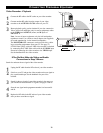
Note : The names of the component video sockets may differ
depending on the DVD player or digital source equipment used.
For example, besides YPbPr, you may see R-Y/B-Y/Y or
CrCbY. Although abbreviations and terms may vary, the letters
B and R stand for the blue and red color component signal con-
nectors, respectively. The Y indicates the luminance signal. If
necessary, see the handbook for the digital equipment for more
information.