


Rear Panel 27
S-VIDEO
(Y/C)
ANTENNA
TV
S-VIDEO
(Y/C)
VIDEO
(CVBS)
VIDEO
(CVBS)
COMPONENT
VIDEO
AUDIO
COMPONENT
VIDEO
AUDIO
Y
P
B
P
R
Y
P
B
P
R
IN - EXT 2 IN - EXT 1
OUT 2 OUT 1
480p/480
i
COAX OUT
G-LINK
DIGITAL AUDIO OUT
OPTICAL OUT
MAINS
AUDIO
L
R
AUDIO
L
R
DIGITAL AUDIO OUT
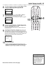
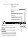
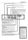
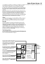
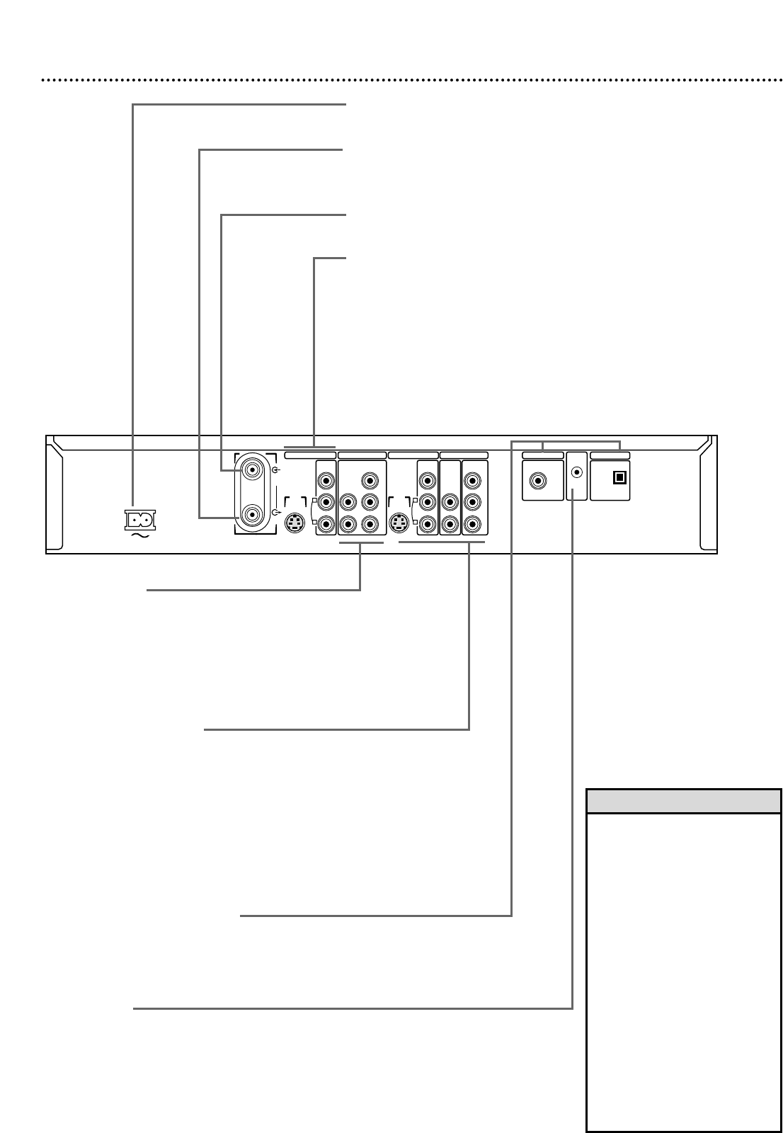
MAINS ~ jack
Connect the supplied AC power cord here. See pages 10-16.
TV jack
Connect the supplied RF coaxial cable to the Recorder’s TV jack and to
the RF IN or ANTENNA IN jack (75 ohm) on your television.
ANTENNA jack
Connect your antenna or Cable TV signal here. See pages 10-16.
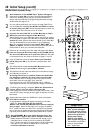
IN EXT 2 jacks
Use these jacks to receive picture and sound from other equipment, such
as a Camcorder or VCR.You will use these if you copy videotapes to a
DVD+R, for example. See page 17. You only need one video connection
from the other equipment, so use eitherVIDEO (CVBS) or S-VIDEO (Y-C).
• VIDEO (CVBS): Use a video cable to connect this jack to the Video
Out jack of other equipment.
• AUDIO L/R (left/right): Connect audio cables here and to the
Audio Out jacks of other equipment.
• S-VIDEO (Y-C): Use an S-video cable to connect this jack to the S-
Video Out jack of other equipment.
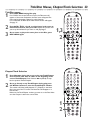
•
Use the same EXT (external)
number for each pair of audio
and video connections. For
example, if you use IN-EXT 2
S-VIDEO (Y/C), use the IN-EXT
2 AUDIO L/R jacks.
IN-EXT means this jack is
bringing IN the audio and video
from an EXTERNAL or sepa-
rate piece of equipment.
•
Do not touch the inner pins of
the jacks. Electrostatic dis-
charge may damage the unit
permanently.
•
You only need one audio and
one video connection to a TV.
You will not use all the jacks.
There are multiple jacks so you
can connect to different TV
styles or to other equipment.
Helpful Hints
IN EXT 1 jacks
Use these jacks to receive picture and sound from other equipment,
such as a Camcorder or VCR,that has Component Video.You will use
these if you copy videotapes to a DVD+R, for example. See page 17.
• AUDIO L/R (left/right): Connect audio cables here and to the
Audio Out jacks of the other equipment.
• COMPONENT VIDEO (Y PB PR): Connect these jacks to the
Component Video Out jacks of the other equipment.
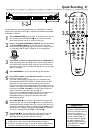
OUT 1 and OUT 2 jacks
Use these jacks to connect the Recorder to your TV and/or Stereo.
• VIDEO (CVBS): Connect the yellow video cable here and to the TV’s
Video In jack. See page 14.
• S-VIDEO (Y-C): Connect an S-Video cable here and to a TV’s S-
Video In jack. See page 13.
• COMPONENT VIDEO (Y P
B PR): Connect Component Video
cables (red, blue, green) here and to a TV’s Component Video In jacks.
See page 12.
• AUDIO L/R (Left/Right): Use audio cables (red, white) to connect
these jacks to the Audio In jacks of a TV or Stereo. See pages 12-15.
DIGITAL AUDIO OUT jacks
• COAX OUT: Connect a digital audio coaxial cable here and to the
digital audio Coaxial In jack of a Stereo. See page 16.
• OPTICAL OUT: Connect a digital audio optical cable here and to
the digital audio Optical In jack of a Stereo. See page 16.
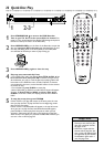
G-LINK jack
Connect the G-Link cable here to have the Recorder operate a Cable
Box for the GUIDE Plus+
®
System. Remove the Demonstration Pin from
this jack first when you receive the Recorder. See pages 18-20.