


Service Modes, Error Codes, and Fault Finding
EN 22 FHP PDP5.
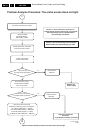
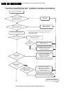
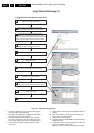
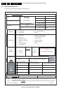
Figure 5-13 Logic Board Exchange (1/2)
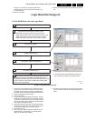
1. Remove the SSB. Now you can reach the cable going to
connector CN01 on the Logic Board.
2. Unplug the LVDS cable from the SSB at connector CN01.
Also unplug the power cable at CN06.
3. Connect the FHP A4 service cable to CN01 and CN06.
Connect the ComPair I2C cable to the CN01 side of the
service cable, and the power cable to the CN06 side of it.
4. Plug in the mains cable. The display starts up in stand-
alone mode.
5. Click the link in ComPair to open the Logic Board exchange
window.
6. Click the 'On' button. In the title bar the module type will
appear: 42A4, or something similar.
7. Click button 'Copy from original'
8. The data is read from the EEPROM on the logic board and
displayed in the list.
9. Use the 'Save' button to save the information to a file. This
is optional, but better safe than sorry!
Note: If you close the window without saving, all settings
Logic Board Exchange (1)
1. Copy NVM Data from defective Logic Board
Remove the Small Signal Board
1.
2.
4.
Set will go into protection or into stand-by
5.
Click the link in ComPair to open the Logic Board
exchange window
6.
Click the "On" button.
In the title bar the module type will appear
7.
Click button "copy from original"
8.
Use the "Save" button to save the information to a file
9.
Click the "Off" button
10.
11.
3.
G_16400_019.eps
010806
Disconnect the LVDS cable from CN01 and
the power cable from CN06 of the Logic Board
Connect the FHP A4 Service cable to CN01
and CN06 of the Logic Board. Reconnect the power
cable from the PSU to the FHP A4 Service cable on the
CN06 side of the Logic Board. Connect the ComPair
cable to the CN01 side of the FHP A4 Service cable.
Plug in the Mains cable to the Mains filter and the
screen will start up in Stand alone mode.
Remove the Mains cable from the Mains filter.