


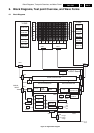
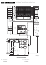

Service Modes, Error Codes, and Fault Finding
EN 23FHP PDP 5.
will be lost. If you intend to close this window before
replacing the board, you should save the settings so you
can load them later.
10. Click the 'Off' button.
11. Switch off the set and replace the Logic Board with another
one.
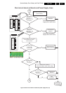
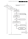
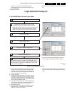
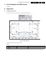
Figure 5-14 Logic Board Exchange (2/2)
1. Switch off the set and replace the Logic Board by another
one. Now connect the service cable to connectors CN01
and CN06. Connect the power cable to the CN06 side of
the service cable, and the ComPair cable to the CN01 side.
2. Restart the display with the new board.
3. Click the 'On' button.
4. The module type will again appear in the title bar. This may
be different now from step 6 on the previous page, because
now another Logic Board is used. If you closed the window
after step 9 and did save the settings you should load them
now. Use the ‘Load’ button to do so.
5. Click button 'Paste to replacement'. The settings previously
copied from the old board are now written to the new board.
If successful the button 'Ship out' will be enabled.
6. Click button 'Ship out'.
7. Now a process of voltage feedback initialization and self-
adjustment starts. This will take a few seconds. When
ready you can switch off the display.
8. Disconnect ComPair and remove the service cable, plug in
the power cable at CN06 and the original LVDS cable at
CN01.
G_16400_020.eps
010806
Logic Board Exchange (2)
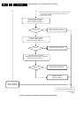
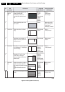
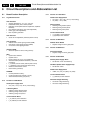
2. Write NVM Data to the new Logic Board
(1) The PDP screen will be blanked for about 15s,
then 15s later, the 'Ship out' process will end
1.
2.
Click the "On" button
3.
Load the saved values
4.
Click button “paste to replacement”
5.
Click button "Ship Out" (1)
6.
7.
Remove the Mains cable from the Mains filter.
Connect the FHP A4 Service cable to CN01
and CN06 of the Logic Board. Connect the power
cable from the PSU to the FHP A4 Service cable on the
CN06 side of the Logic Board. Connect the ComPair
cable to the CN01 side of the FHP A4 Service cable.
Disconnect the ComPair cable and Power cable from the
FHP A4 Service cable on the CN01 and CN06 sides of the
Logic Board. Disconnect the FHP A4 Service cable. Reconnect
the Power cable from the PSU to CN06 and the LVDS cable
to CN01 on the Logic Board.