Philips Semiconductors Product data sheet
SCC2691Universal asynchronous receiver/transmitter (UART)
2006 Aug 04
12
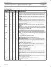
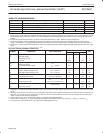
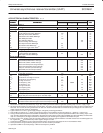
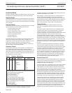
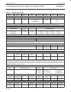
Table 2. Register Bit Formats (Continued)
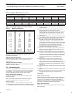
CTUR (Counter/Timer Upper Register)
C/T[15] C/T[14] C/T[13] C/T[12] C/T[11] C/T[10] C/T[9] C/T[8]
Bit 7 Bit 6 Bit 5 Bit 4 Bit 3 Bit 2 Bit 1 Bit 0
CTLR (Counter/Timer Lower Register)
C/T[7] C/T[6] C/T[5] C/T[4] C/T[3] C/T[2] C/T[1] C/T[0]
CSR – Clock Select Register (see Table 6. also)
Table 3. Baud Rate Selection
CSR[3:0]/ [7:4] ACR[7] = 0 ACR[7] = 1
0 0 0 0 50 75
0 0 0 1 110 110
0 0 1 0 134.5 134.5
0 0 1 1 200 150
0 1 0 0 300 300
0 1 0 1 600 600
0 1 1 0 1,200 1,200
0 1 1 1 1,050 2,000
1 0 0 0 2,400 2,400
1 0 0 1 4,800 4,800
1 0 1 0 7,200 1,800
1 0 1 1 9,600 9,600
1 1 0 0 38.4k 19.2k
1 1 0 1 Timer Timer
1 1 1 0 MPI – 16X MPI – 16X
1 1 1 1 MPI–1X MPI–1X
The receiver clock is always a 16X clock, except for CSR[7:4] = 1111.
See
“Extended baud rates for SCN2681, SCN68681, SCC2691,
SCC2692, SCC68681 and SCC2698B”
in application notes
elsewhere in this publication
CSR[7:4] – Receiver Clock Select
This field selects the baud rate clock for the receiver as shown in
Table 3. The baud rates listed are for a 3.6864MHz crystal or
external clock.
CSR[3:0] – Transmitter Clock Select
This field selects the baud rate clock for the transmitter. The field
definition is as shown in Table 3.
CR – Command Register
CR is used to write commands to the UART. Multiple commands can
be specified in a single write to CR as long as the commands are
non-conflicting, e.g., the enable transmitter and reset transmitter
commands cannot be specified in a single command word.
CR[7:4] – Miscellaneous Commands
The encoded value of this field may be used to specify a single
command as follows:
NOTE: Access to the upper four bits of the command register
should be separated by three (3) edges of the X1 clock.
0000 No command.
0001 Reset MR pointer. Causes the MR pointer to point to MR1.
0010 Reset receiver. Resets the receiver as if a hardware reset had
been applied. The receiver is disable and the FIFO is flushed.
0011 Reset transmitter. Resets the transmitter as if a hardware reset
had been applied
0100 Reset error status. Clears the received break, parity error,
framing error, and overrun error bits in the status
register (SR[7:4]}. Used in character mode to clear OE status
(although RB, PE, and FE bits will also be cleared), and in
block mode to clear all error status after a block of data has
been received.
0101 Reset break change interrupt. Causes the break detect change
bit in the interrupt status register (ISR[3]) to be cleared to zero.
0110 Start break. Forces the TxD output low (spacing). If the
transmitter is empty, the start of the break condition will be
delayed up to two bit times. If the transmitter is active, the
break begins when transmission of the character is completed.
If a character is in the THR, the start of break is delayed until
that character or any others loaded after it have been
transmitted (TxEMT must be true before break begins). The
transmitter must be enabled to start a break
0111 Stop break. The TxD line will go high (marking) within two bit
times. TxD will remain high for one bit time before the next
character, if any, is transmitted.
1000 Start C/T. In counter or timer modes, causes the contents of
CTUR/CTLR to be preset into the counter/timer and starts the
counting cycle. In timer mode, any counting cycle in progress
when the command is issued is terminated. In counter mode,
has no effect unless a stop C/T command was issued
previously.
1001 Stop counter. In counter mode, stops operation of the
counter/timer, resets the counter ready bit in the ISR, and
forces the MPO output high if it is programmed to be the
output of the C/T. In timer mode, resets the counter ready bit in
the ISR but has no effect on the counter/timer itself or on the
MPO output.
1010 Assert RTSN. Causes the RTSN output (MPO) to be asserted
(low).
1011 Negate RTSN.Causes the RTSN output (MPO) to be negated
(high).
1100 Reset MPI change interrupt. Causes the MPI change bit in the
interrupt status register (ISR[7]) to be cleared to zero.
1100 Reserved.
111x Reserved.
CR[3] – Disable Transmitter
This command terminates operation and resets the TxRDY and
TxEMT status bits. However, if a character is being transmitted or if
a character is in the THR when the transmitter is disabled, the
transmission of the character(s) is completed before assuming the
inactive state. A disabled transmitter cannot be loaded.
CR[2] – Enable Transmitter
Enables operation of the channel A transmitter. The TxRDY status
bit will be asserted.


