


Functional overview -
Product illustrations on inside flap
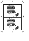
A)Transmitter unit
1 Power light
Lights green when power is switched on.
2 Remote control receiver light
Blinks red when a remote control signal is received.
3 ON/OFF switch
Switches the transmitter unit on and off.
4 DC 9V —<±
DC power supply socket for connection to the mains
5 AV SOURCE INPUT connectors
For connecting to an RCA or SCART enabled video source.
VIDEO (yellow) - video input connector
R-AUDIO-L - left (L) and right (R) audio input connectors
(R-red / L-white)
6 CHANNEL switch
Selects the desired frequency channel of the audio/video signal.The
number of channels you can select may vary from country to country.
7IR
For connecting the remote control blaster cord if the video source does
not respond to signals from the remote control.
8 AC power adapter
B)Receiver unit
9 Power light
Lights green when power is switched on.
10 Remote control receiver light
Blinks red when a remote control signal to be transmitted to the video
source via the transmitter is received.
11 ON/OFF switch
Switches the receiver unit on and off.
12 DC 9V —<±
DC power supply socket for connection to the mains
13 TV OUTPUT connectors
For connection to an RCA or SCART enabled TV.
VIDEO (yellow) - video output connector.
R-AUDIO-L - left (L) and right (R) audio output connectors
(R-red / L-white).
14 CHANNEL switch
Selects the desired frequency channel of the audio/video signal.
The number of channels you can select may vary per country.
15 AC Power adapter
ENGLISH6
XP SBC VL1100 07-02-2003 12:48 Pagina 6