


Getting your Wireless TV Link ready
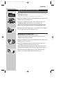
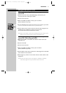
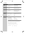
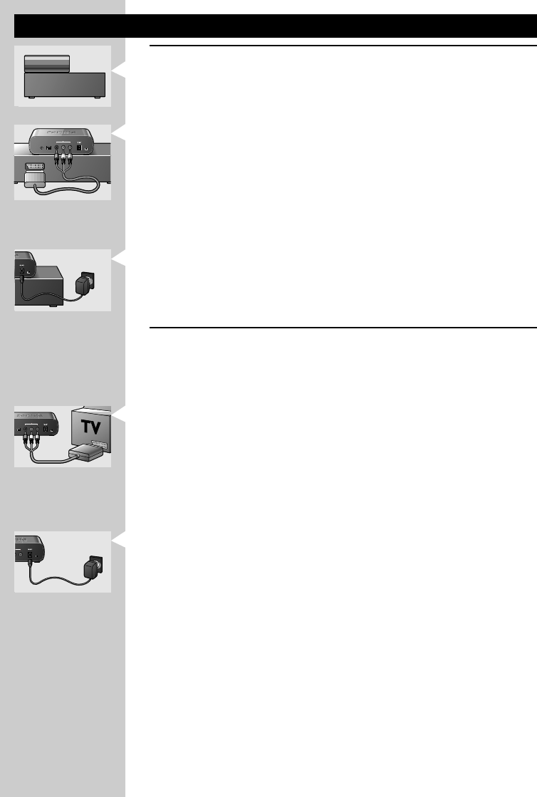
Setting up the transmitter unit
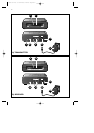
1 Position the transmitter unit on top of the video source with the front
panels aligned vertically.
Never put video sources or metal plates on the transmitter unit.
2 Connect the SCART connector of the SCART/RCA cable supplied to the
SCART output of the video source.
3 Connect the audio/video plugs at the other end of the cable to the
AV SOURCE INPUT connectors (5) on the transmitter unit.
Be sure to insert the yellow plug into the yellow video input and the
white and red audio plugs into the left (L) and right (R) audio inputs.
4 Connect the AC power adapter (8) to a mains socket and to the DC 9V
—<± supply socket (4) of the transmitter unit.
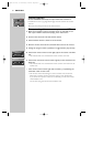
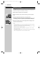
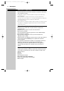
Setting up the receiver unit
1 Position the receiver unit close to the second TV.
The front of the receiver unit should be positioned so that remote
control commands can be received.
2 Connect the SCART connector of the SCART/RCA cable supplied to the
SCART input of the second TV.
3 Connect the audio/video plugs at the other end of the cable to the
TV OUTPUT connectors (13) on the receiver unit.
Be sure to insert the yellow plug into the yellow video input and the
white and red audio plugs into the left (L) and right (R) audio inputs.
4 Connect the AC power adapter (15) to a mains socket and to the
DC 9V —<± supply socket (12) of the transmitter unit.
ENGLISH 7
1 2 3 4
1 2 3 4
AV SOURCE INPUT
R–AUDIO–L
CHANNEL
IR
VIDEO DC 9V
ON/OFF
AV SOURCE INPUT
R–AUDIO–L
CHANNEL
IR
VIDEO DC 9V
ON/OFF
SCART OUTPUT
SCART OUTPUT
DC 9V
ON/OFF
DC 9V
ON/OFF
1 2 3 4
1 2 3 4
R–AUDIO–L
CHANNEL
VIDEO DC 9V
ON/OFF
R–AUDIO–L
TV OUTPUT
TV OUTPUT
CHANNEL
VIDEO DC 9V
ON/OFF
T
PUT
VIDEO DC 9V
ON/OFF
T
PUT
VIDEO DC 9V
ON/OFF
XP SBC VL1100 07-02-2003 12:48 Pagina 7