09
58
En
Chapter 9
Additional information
Serial interface
specifications
In addition to the basic operations on the player's front
panel and remote control, the player is equipped with a
serial interface conforming to RS-232C standards allowing
connection to a computer. The interface is a 9-pin D-Sub
connector.
Caution
•The 9-pin connector uses inch screw threads.
The D-Sub connector's pin layout is as shown below.
Serial control specifications
(1) Signal level
RS-232C level
(2) Data format
Data length: 8 bits
Stop bit: 1 bit
Parity: None
(3) Communication speed (Baud rate)
The communication speed (Baud rate) is selectable
among the following: 2400 bps, 4800 bps, 9600 bps,
19200 bps and 115200 bps. Set to 9600 bps by
factory default (page 56).
Connection to a computer
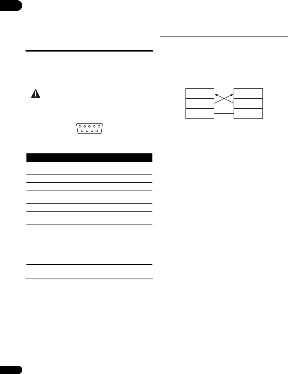
The player communicates with the computer using the
9-pin D-Sub connector's pins 2 and 3 for signal transfer
and pin 5 as the ground.
The computer and player are connected as shown on the
diagram below.
The player can accept commands whenever the power is
on. In addition, the player can accept the commands
below even when the power is off.
•Power ON command
•Play command
• Commands with the power (A181AFBC), play
(A181AF39) and power on (A181AFBA) Remote
Control Button commands as arguments.
There is no need to connect control lines other than TxD
and RxD.
Pin no. Terminal Input/Output
Function
1DCDInput NC (not connected on
the player)
2RxD Input receive data
3 TxD Output send data
4DTR Output NC (not connected on
the player)
5 GND -- ground
6DSRInput NC (not connected on
the player)
7RTS Outupt Connected to CTS pin
internally.
8CTS Input Connected to RTS pin
internally.
9RI Input NC (not connected on
the player)
51
69
RxD
TxD
GND
BDP-V6000
RxDPin 2
Pin 3
Pin 5
Pin 2
Pin 3
Pin 5
TxD
GND
Control terminal such as
a computer
V6000_CUXJ_EN.book 58 ページ 2009年6月5日 金曜日 午前11時57分


