


7
PRO-1000HDI / PRO-800HDI
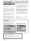
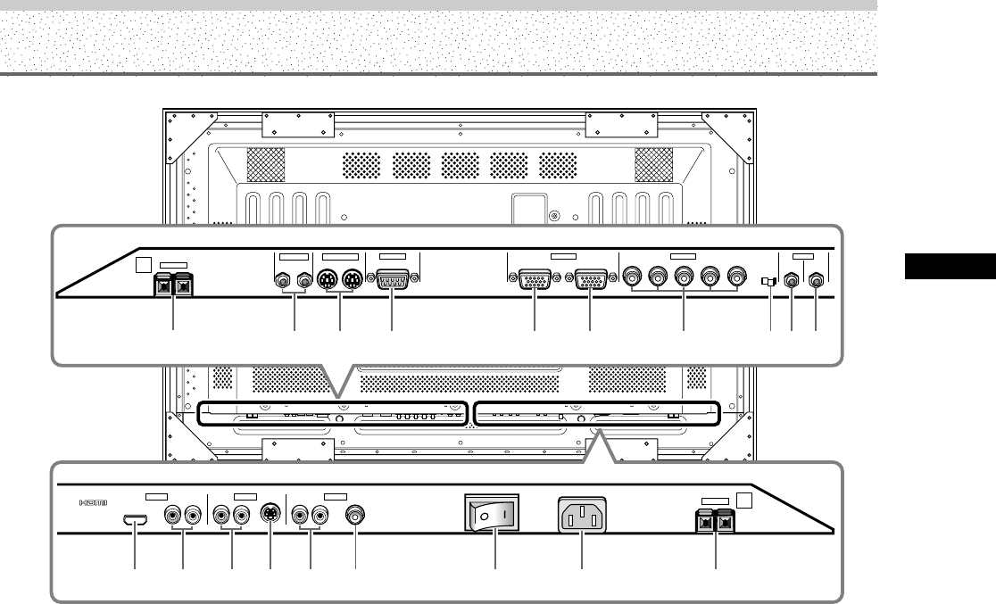
Part Names and Functions
Part Names and Functions
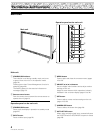
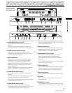
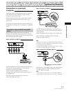
9 AUDIO INPUT (Stereo mini jack)
Use to obtain sound when INPUT1 or INPUT2 is
selected.
Connect the audio output terminal of components
connected to INPUT1 or INPUT2 to this unit (page 15).
0 AUDIO OUTPUT (Stereo mini jack)
Use to output the audio of the selected source
component connected to this unit to an AV amplifier
or similar component (page 15).
- INPUT5 (HDMI jack)
For connection of components that have a digital
video output terminal sach as a digital set top box,
DVD player, etc. compatible with HDCP. Before
attempting to connect one of these devices, read its
operating instructions to make sure that it can be
connected (page 13).
(HDCP = High-brandwidth Digital Content Protection)
(HDMI = High Definition Multimedia Interface)
= AUDIO INPUT5 (RCA Pin jacks)
Use to obtain sound when INPUT5 (analog audio) is
selected.
Connect these jacks to the audio output connectors of
components connected to INPUT5 (page 15).
Note: The left audio channel (L) jack is not compatible
with monaural input sources.
~ AUDIO INPUT3 (RCA Pin jacks)
Use to obtain sound when INPUT3 is selected.
Connect these jacks to the audio output connectors of
components connected to INPUT3 (page 15).
Note: The left audio channel (L) jack is not compatible
with monaural input sources.
! INPUT3 (S-video jack)
For connection of components that have an S-video
output terminal such as a video deck, video camera,
LaserDisc player, or DVD player. (page 13)
@ AUDIO INPUT4 (RCA Pin jacks)
Use to obtain sound when INPUT4 is selected.
Connect these terminals to the audio output
connectors of components connected to INPUT4
(page 15).
Note: The left audio channel (L) jack is not compatible
with monaural input sources.
# INPUT4 (BNC jack)
For connection of components that have a composite
video output terminal such as a video deck, video
camera, LaserDisc player, or DVD player (page 13).
$ Main power switch
Use to switch the main power of the unit on and off.
% AC INLET
Use to connect the supplied power cord to an AC
outlet (page 16).
^ SPEAKER (L) terminal
For connection of an external left speaker. Connect a
speaker that has an impedance of 8 –16 Ω (page 14).
@
!
-~
1234 5 67890
IN OUT
CONTROL
COMBINATION
IN OUT
RS-232C
ANALOG RGB (ANALOG RGB)
INPUT1
OUTPUT
GBRHDVD
(ON SYNC) (H/V SYNC)
S-VIDEO VIDEO
Ô
75 2.2
Ω kΩ
INPUT
(INPUT1/2)
OUTPUT
R
SPEAKER
8Ω ~16Ω
+ –
INPUT3INPUT5 INPUT4
INPUT2 AUDIO
AUDIO
R
L
AUDIO
R
L
AUDIO
L
R
HDMI
^%$
L
AC INLET
SPEAKER
8Ω ~16Ω
+ –
=
#
Illustration depicts
PRO-1000HD
I model.