


9
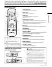
PRO-1000HDI / PRO-800HDI
Installation and Connections
Installation and Connections
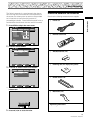
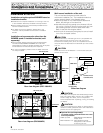
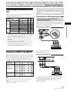
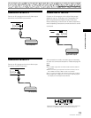
Connection to INPUT1 and INPUT2
Various components can be connected to the INPUT1 and
INPUT2 terminals. After connections are made, on-screen
setup is necessary to match the characteristics of the
connected component. Please see pages 18 and 19 for
on-screen setup after connection.
Note
Components compatible with INPUT1 are also compatible with
INPUT2.
When making connections to INPUT1, please refer to
supplement 4 on page 42.
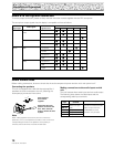
: Do not connect anything. : Connect to this jack.
INPUT2 terminal
Output source
[ON SYNC]
GBR
[H/V SYNC]
HD VD
Video component/
Personal
computer (PC)
with RGB output
G ON SYNC
R
RG
GBR
B
B
VD
H/V SYNC
HD
YCB/PB CR/PR
Video component
with component
video output
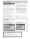
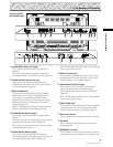
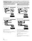
About the Input Connectors on this
Unit
Consult the following chart when making connections to
a plasma display (pages 9 to 16).
*1 Although INPUT1/INPUT2 are compatible with various kinds
of signals, setup using the on-screen menu is necessary after
connections are made in order match the characteristics of
the source component (pages 18 and 19).
*2 INPUT1 is compatible with Microsoft’s Plug & Play (VESA
DDC 1/2B).
*3 Depending on the video output board of the computer, this
type of connection may not be possible.
*4 Although INPUT5 is compatible with various kinds of signals,
setup using the on-screen menu is necessary after
connections are made in order match the characteristics of
the source component (pages 20 and 21).
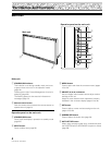
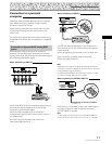
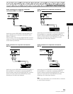
Connection to AV components
Connection to AV component that has
component video jacks
Make component video connections for AV components
such as DVD and LD players or similar components with
component video output capability.
When connecting to INPUT1
On-screen setup is necessary after connection.
Please see page 18.
When connecting to INPUT2
Connect the Y signal to the G terminal, the CB/PB signal to
the B terminal, and the C
R/PR signal to the R terminal.
On-screen setup is necessary after connection.
Please see page 18.
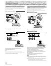
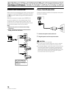
ANALOG RGB (ANALOG RGB)
INPUT1
OUTPUT
GBRHD VD
(ON SYNC) (H/V SYNC)
Ô
75 2.2
Ω kΩ
INPUT2
INPUT
4
INPUT
3
*3
*3
Input Connector
INPUT
1
*1
INPUT
2
*1
Analog RGB
Component video
S video
Composite video
Digital video
Personal
computer
(PC)
AV
component
Connected
component and signals
Analog RGB
S video
Composite video
*2
INPUT
5
*5
*4
For the screen sizes and input signals that INPUT1
and INPUT2 are compatible with, please refer to
supplement 1 (pages 39 to 40) and supplement 2
(page 41).