


8
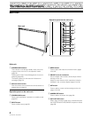
PRO-1000HDI / PRO-800HDI
Installation and Connections
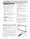
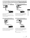
Installation of the Unit
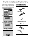
7 Optional line (sold separately)
(For details, please consult the dealer where this
unit was purchased.)
1 Table top stand : PRO-1000HDI / PRO-800HDI
display stand.
2 Wall installation unit: Wall installation bracket
designed as a wall interface
for securing the unit.
Installation using the optional PIONEER stand or
installation bracket
÷ Please be sure to request installation or mounting of this unit
or the installation bracket by the dealer where purchased.
÷ When installing, be sure to use the bolts provided with the
stand or installation bracket.
÷ For details concerning installation, please refer to the
instruction manual provided with the stand or installation
bracket.
Installation using accessories other than the
PIONEER stand or installation bracket (sold
separately)
÷ When possible, please install using parts and accessories
manufactured by PIONEER. PIONEER will not be held
responsible for accident or damage caused by the use of parts
and accessories manufactured by other companies.
÷ For custom installation, please consult the dealer where the
unit was purchased.
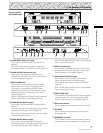
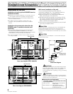
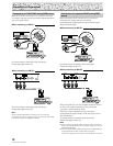
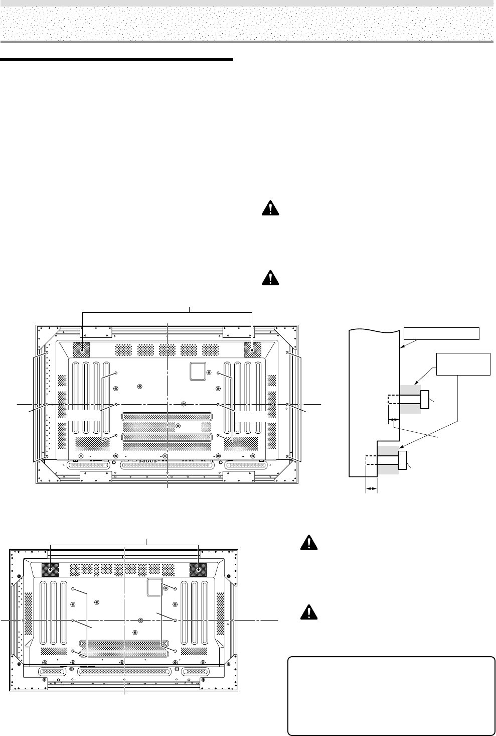
Wall-mount installation of the unit
This unit has been designed with bolt holes for
wall-mount installation, etc.. The installation holes that
can be used are shown in the diagram below.
÷ Be sure to attach in 4 or more locations above and
below, left and right of the center line.
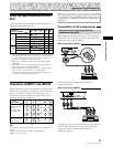
÷ Use bolts that are long enough to be inserted 1/2 inch
(12 mm) to 11/16 inch (18 mm) into the main unit from
the attaching surface for both a holes and b holes.
Refer to the side view diagram below.
÷ As this unit is constructed with glass, be sure to install
it on a flat, unwarped surface.
CAUTION
To avoid malfunction, overheating of this unit, and possible fire
hazard, make sure that the vents on the main unit are not
blocked when installing. Also, as hot air is expelled from the air
vents, be careful of deterioration and dirt build up on rear surface
wall, etc..
CAUTION
Please be sure to use an M8 (Pitch = 1.25 mm) bolt. (Only this
size bolt can be used.)
Main unit
b hole
Center line
b hole
Center line
a hole
b hole
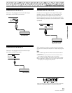
Bolt
Bolt
Attaching surface
Installation
bracket, etc..
1/2 inches (12 mm) to
11/16 inches (18 mm)
1/2 inch (12 mm) to
11/16 inch (18 mm)
Rear view diagram (PRO-1000HDI)
Side view diagram
a hole
a hole
Air vents (fan)
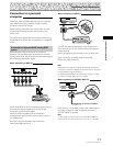
CAUTION
This display unit weighs at least 67 lbs (30 kg) and has
little front-to-back depth, making it very unstable when
stood on edge. As a result, two or more persons
should cooperate when unpacking, moving, or installing
the display.
CAUTION
This unit incorporates a thin design. To ensure safety if
vibrated or shaken, please be sure to take measures to
prevent the unit from tipping over.
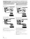
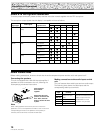
Center line
Center line
a hole
a hole
Air vents (fan)
Rear view diagram (PRO-800HDI)