


Connecting up
02
53
En
English
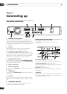
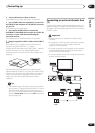
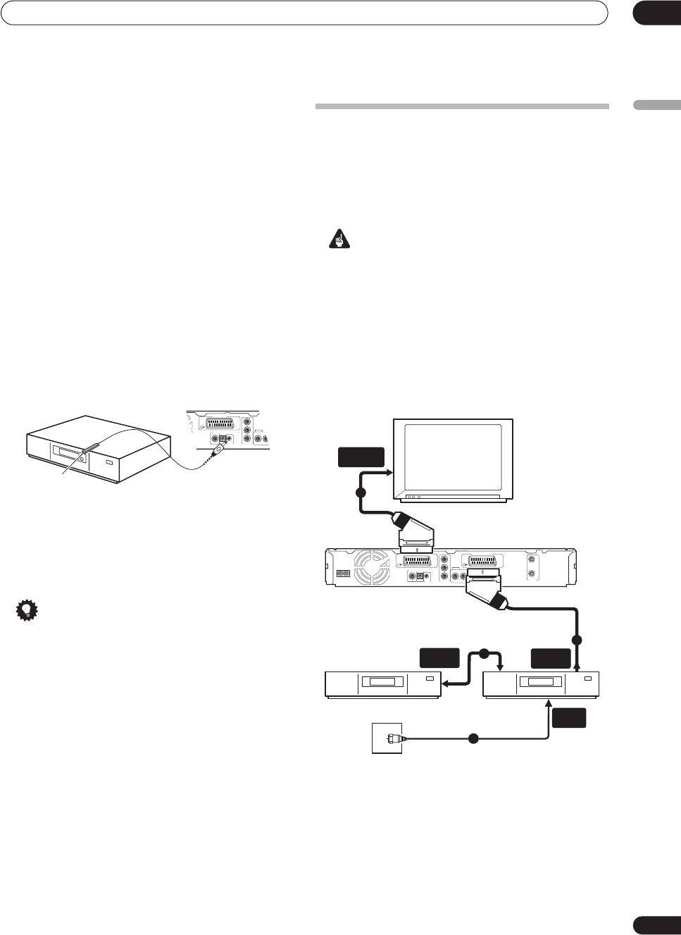
1 Connect RF antenna cables as shown.
This enables you to watch and record TV channels.
2 Use a SCART cable (not supplied) to connect the
AV1(RGB)-TV AV connector to a SCART AV connector
on your TV.
This enables you to watch discs.
3 Use another SCART cable to connect the
AV2(INPUT 1/DECODER) AV connector to a SCART AV
connector on your cable box/satellite/digital
terrestrial receiver.
This enables you to record scrambled TV channels.
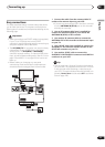
4 Plug the supplied G-LINK™ cable to the G-LINK™
jack.
This enables you to control the tuner in the external
receiver using the GUIDE Plus+™ system.
Position the IR transmitter end of the G-LINK™ cable so
that the IR receiver on your cable/satellite/digital
terrestrial receiver will pick up the control signals (see
diagram).
See the manual that came with your cable/satellite/
digital terrestrial receiver if you’re not sure where the IR
receiver is on the front panel. Alternatively, experiment
with the remote control, operating it from very close
range until you find the place where the receiver
responds.
Tip
• This recorder has a ‘through’ function which allows
you to record a TV program from the built-in TV tuner
in this recorder while watching a video playing on
your VCR. (To use this feature when the recorder is in
standby, Power Save must be set to Off—see Power
Save on page 128).
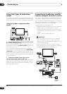
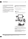
Connecting an external decoder box
(1)
If you have an external, dedicated decoder box for your
satellite or cable TV system, use the setup described on
this page. See the previous page for how to connect the
G-LINK™ cable.
Important
• Do not connect your decoder box directly to this
recorder.
• Information from the decoder (for example, relating
to pay TV services), is only viewable when this
recorder is off (in standby).
• For timer recording to work properly on this recorder,
the VCR/satellite receiver/cable box must also be
switched on during recording.
• It is not possible to watch one TV program and record
another using this setup.
DIGITAL
OUT
CONTROL
G-LINK
COAXIAL IN
AUDIO
L
R
COMPONENT
VIDEO OUT
Y
P
B
PR
OUTPUT
AV 1 (RGB) – TV
G-LINK cable
TV
Antenna/cable TV
wall outlet
VCR/Satellite receiver
/Cable box
Decoder
AC IN
DIGITAL
OUT
CONTROL
G-LINK
COAXIAL IN
S-VIDEO
VIDEOAUDIO
LR
COMPONENT
VIDEO OUT
Y
P
B
PR
ANTENNA
IN
OUT
OUTPUT
AV 1 (RGB) – TV AV 2 (INPUT 1/DECODER)
SCART AV
CONNECTOR
SCART AV
CONNECTOR
SCART AV
CONNECTOR
ANTENNA
IN
1
4
2
3