


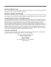
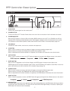
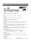
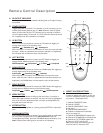
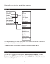
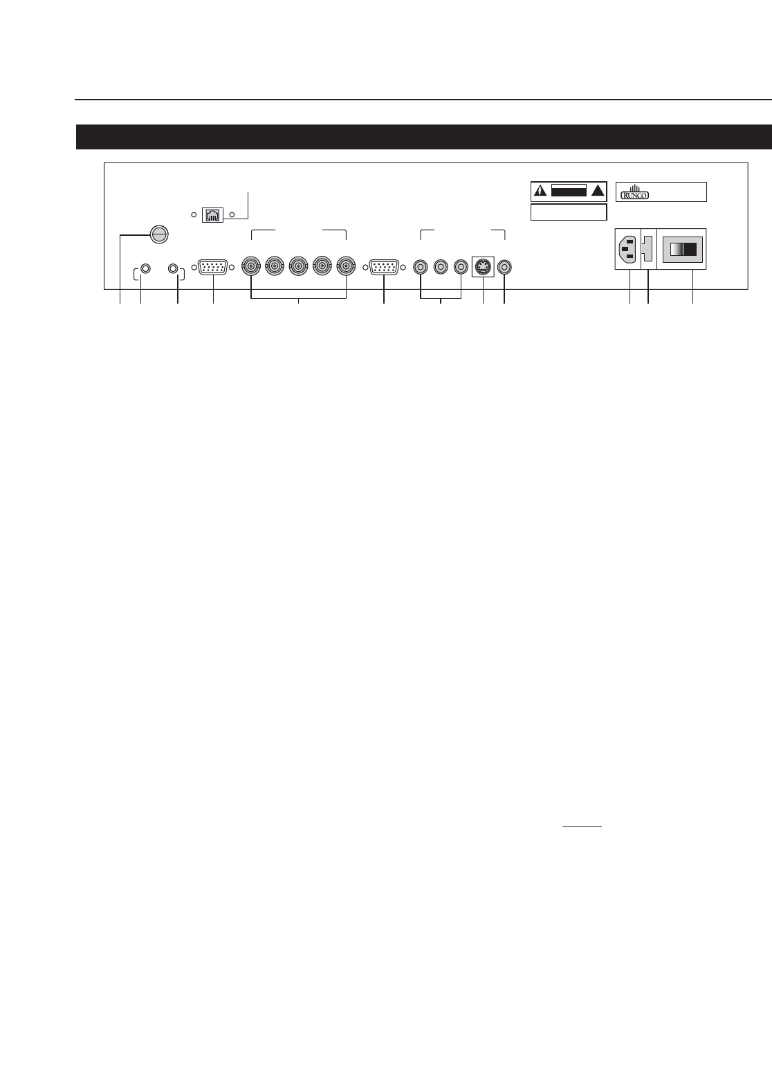
Rear Panel
12V TRIGGER
12V FUSE
RGB OUTPUT VIDEO INPUTS
RS-232 IN
MADE IN USA
AC 120V 60Hz, 15W
MASK
SCREEN
RGB/COMPONENT COMPOSITEV
H
B G R Y Pr Pb
S-VIDEO
MADE IN USA
RUNCO INTERNATIONAL
HAYWARD, CA
CAUTION: TO REDUCE THE RISK OF ELECTRIC
SHOCK, DO NOT REMOVE COVER. NO USER-
SERVICEABLE PARTS INSIDE. REFER SERVICING
TO QUALIFIED SERVICE CENTER.
AVIS: RISQUE DE CHOC ELECTRIQUE-NE PAS OUVRIR
CAUTION
RISK OF ELECTRIC SHOCK
DO NOT OPEN
!
WARNING: TO REDUCE THE RISK OF FIRE
OR ELECTRIC SHOCK, DO NOT EXPOSE
THIS APPLIANCE TO RAIN OR MOISTURE.
6 7 8 9 1042 31
5
11 12
13
COMLINK OUT
12
1. 12v FUSE
This fuse protects the 12v outputs from the MASK and SCREEN jacks.
(Screen Fuse: 5mm x 25mm, AGC, 0.5A, 250V, Fast Blow)
2. MASK
This is a 12V output that can be used to trigger curtains, lifts, etc. (1/4A maximum load).
3. SCREEN
This is a 12V output that can be used to trigger curtains, lifts, etc. (1/4A maximum load).
4. RS-232 IN
This is for systems using serial (RS-232) to control the PFP Controller.
Please refer to page 27 for RS-232 protocol and information.
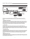
5. COMLINK OUT
The output of this jack must be connected to the ComLink input of the DR-300c. If this is not connected, neither
the PFP Controller or the Projector can operate and the power indicator on the front panel will stay yellow.
6. RGB OUTPUT
This is the main output of the PFP Controller. The RGB Signal goes directly to the Projector. If
Component is used through the RGB/Component, then only the R (Pr), G(Y) and B(Pb) jacks will be active.
Individually, the jacks are: V=vertical sync, H=horizontal sync, B=Blue, G=Green, R=Red.
7. RGB/COMPONENT
Anything input to this port will by-pass the processing of the PFP Controller and be sent straight to the dis-
play. This is useful for computer graphics and HDTV signals which do not require processing.
8. COMPONENT INPUT
This is the input for Component Video from sources such as DVD players.
Note: The component output from a DTV decoder or a progressive-scan DVD cannot
be used with this port;
it must be used with the
RGB/Component port.
9. S-VIDEO INPUT
This is the input for S-Video from sources such as Satellite receivers, S-VHS VCR’s and DVD players.
10. COMPOSITE VIDEO INPUT
This is the input for Composite Video from sources such as laser disc players, VCRs and other misc. sources.
11. POWER INPUT
Plug in Main Power here.
12. 115 VAC FUSE 13. MAIN POWER SWITCH
This is the main AC Input fuse (.5A/250V). Disconnects or applies main power to the Controller.