


Controls and Functions
8 Vistage™ Series Flat-Panel Display Installation/Operation Manual
PRE
L
IMINAR
Y
2.3
DHD Controller Rear
Panel
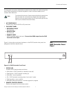
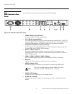
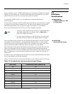
Figure 2-5 shows the rear connector panel on the DHD Controller.
Figure 2-5. DHD Controller Rear Panel
1. POWER INPUT (100 to 240 VAC)
Connect the DHD Controller to power here.
2. HD1 / HD2 (5 x Analog BNCs)
Two inputs (five BNCs per input) for connecting standard-definition (SD = 480i/576i),
enhanced-definition (ED = 480p/576p) or high-definition (HD = 720p/1080i/1080p)
component video sources, or RGBHV sources such as personal computers.
3. Component / SCART (3 x RCA connectors)
SD/HD input for connecting SDTV, EDTV or HDTV component video sources. Also
provides RGB input for SCART RGBS sources.
4. Video 1 / Video 2 / Video 3
Standard, composite video inputs for connecting a VCR, camcorder or other
composite video source. The Video 1 input also provides composite sync input for
SCART RGBS sources.
5. HDMI 1 / HDMI 2 / HDMI 3 / HDMI 4 (Digital)
HDCP-compliant digital video inputs for connecting an HDMI or DVI source.
6. Ethernet
A female RJ-45 connector for wired network communications.
7. HDMI Out (Audio Only)
Connect this output to an audio control system to pass through HDMI audio.
8. HDMI Out (To Display)
Connect this to an HDMI input on your display device.
9. RS-232 (PC / Control)
A female, 9-pin D-sub connector for interfacing with a PC or automation/control
system.
Video 1Y Video 2
Video 3
Pr
Pb
PC / Control
RS-232
HDMI 2
HDMI 4
Ethernet
HDMI Out
To Display
HDMI Out
Audio Only
HD1
HD2
deo
Y
Vi
deo
1
P
r
Pb
1
2
Vi
deo
1
H
H
96
2
1
HDMI
2
HDMI
4
HDMI
2
HDMI
4
5
38
7
4
V
i
d
eo
2
Vi
deo
3
Vi
deo
1
1
Vi
d
1
The DHD Controller does not transmit HDMI CEC control
messages from the “HDMI Audio Out” connector.
Note