11
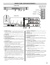
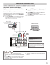
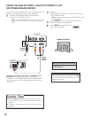
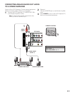
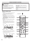
FRONT, SIDE, AND BACK PANELS
POWER
LAMP
REPLACE
WARNING
POWER
FRONT PANEL
S-VIDEO
VIDEO
R-AUDIO-L
(MONO)
Y–––––Pb–––––Pr
VIDEO
3
VIDEO
2
VIDEO
1
WOOFER
AUDIO
OUTPUT
SERVICE
DIGITAL
ANTENNA IN
DIGITAL
AUDIO
OUTPUT
HDMI
UHF/VHF/CATV
Y–––––Pb–––––Pr
R-AUDIO-L
(MONO)
R-AUDIO-L
(MONO)
R-AUDIO-L
(MONO)
RIGHT SIDE PANEL
q
BACK PANEL
VOLUME + – keys
CHANNEL + – keys
(See items 1, 8, & 17
on pages 18 & 19.)
CHANNEL
–
+
VOLUME
–
+
INPUT
INPUT key
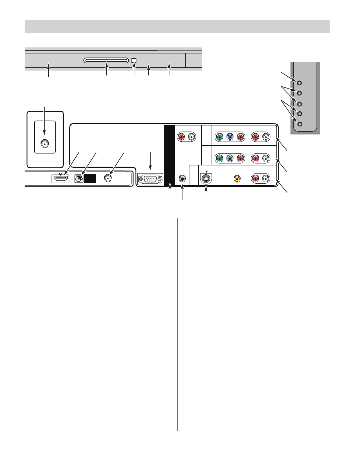
w e r t
y
u i o !0
!2 !3
!6
!5
!4
!1
q
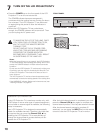
POWER indicator— A green light indicates the LCD
Projection TV is on; red light indicates the AC power
cord is connected, but the LCD Projection TV is in the
off condition.
w
POWER key—Turn the LCD Projection TV on or off.
e
Infrared Remote Receiver—Receives the signal from
the remote control.
r
LAMP REPLACE indicator—A yellow light indicates
the lamp has reached the end- of-life. The lamp needs
to be replaced.
t
WARNING indicator—A red light indicates the LCD
Projection TV detects an abnormal condition. A
flashing red light indicates that the internal
temperature of LCD Projection TV exceeds the normal
operating range.
y
Analog Antenna Input (UHF/VHF/CATV)—Connect
an RF antenna or Analog cable system to this jack.
u
HDMI (High Definition Multimedia Interface)
Input—Connect digital video equipment to this jack. It
takes only one high bandwidth cable (not supplied) to
communicate between audio/video equipment and
this LCD Projection TV. This connection is compatible
with DVI equipped devices. (Separate audio
connection and an adapter are required for a DVI
device.)
i
DIGITAL AUDIO OUTPUT—Use an Optical Audio
cable to connect Digital Audio Output to an advanced
stereo home theater system equipped with Dolby®
Digital 5.1.
o
DIGITAL ANTENNA IN—Connect an RF antenna to
this jack.
!0
SERVICE Jack—This jack is used to service the LCD
Projection TV.
!1
Analog AUDIO OUTPUT (L/R)—Connect external
audio equipment here.
!2
WOOFER—Connect external audio amplifier to this
jack. This jack outputs woofer sound from TV and the
audio input terminals.
!3
S-VIDEO Input (VIDEO1)—To enhance video detail,
use the S-Video jacks instead of the Video jacks, if
available on your external equipment. (S-Video
connection will override connection to the VIDEO
input jack [VIDEO1]).
!4
AUDIO/VIDEO Input (VIDEO1)—Connect analog
video equipment here.
Note: S-Video connection overrides the (VIDEO1)
composite video connection.
!5
Component Video Input (VIDEO2)—Connect digital
video equipment to the Y, Pb, Pr, and Audio L/R jacks.
These jacks will automatically detect the type of
signal being received.
!6
Component Video Input (VIDEO3)—Connect digital
video equipment to the Y, Pb, Pr, and Audio L/R jacks.
These jacks will automatically detect the type of
signal being received.


