


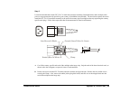
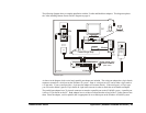
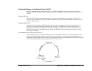
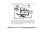
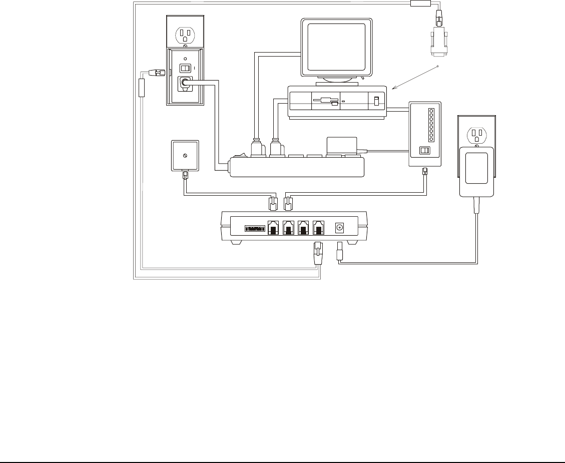
The following diagram shows a complete installation with the Y-cable and ShutDown adapter. This diagram replaces the
"After installing Remote Power On/Off" diagram on page 14.
PC
OFF ON
ON OFF
Power/Surge Strip
Telephone Cables
To
Modem
Line-In
Telephone
Wall Jack
Modem
Power
Supply
ON OFF
OFF
ON
MR
TR
SD
RD
OH
CD
AA
HS
IPM
Power On/Off +
ShutDown/reBOOT
Aux
(back view)
IPM Signal
D
IP
S
WITCHES
L
INE
M
ODEM
A
UX
IPM P
ORT
P
OWER
STATUS
I
NT ELL IGENT
P
OWER
M
ODULE
0
Power
Supply
ShutDown Signal
Y-Cable
Blue
Red
To Serial Port
NT
NT/NW
As shown in the diagram, a serial port adapter labeled "NT/NW" is included. This serial port adapter has a 9-pin female
connector to attach to a serial port on the Windows NT/2000/XP system. The PPNT system with this adapter is also
capable of notifying certain Novell Netware systems to shut down (hence the "NW" on the adapter). For information
about shutting down a Novell Netware system, please contact Server Technology's Technical Support Department.
Note: A serial port on a PC can be either a 9-pin male or a 25-pin male connector. If your systems provides a 9-pin port
the adapter will connect directly. If the serial port is a 25-pin type, you will need to obtain a generic 25-pin female to 9-
pin male converter in order to attach the ShutDown adapter.
Remote Power On/Off Appendix C | Windows NT/2000/XP ShutDown • 48