


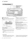
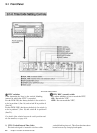
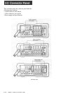

2-2 Connector Panel
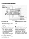
PHONE LEVEL control knob
AUDIO IN connectors (XLR in)
This adjusts the level of audio output to the
EARPHONE and HEADPHONES jacks.
These input up to four analog audio signals from
external microphones or other equipment.
+48 V switches (DVW-250P only) AUDIO OUT connectors
For each of the four channels, these turn on or off the
48 V microphone phantom power supply to the
corresponding AUDIO IN connector. These switches
are only effective when the following selections are
made:
CAMERA/LINE switch: CAMERA position
Audio input level switch: -60 dB position
CAMERA/LINE switches
For each of the four audio channels, these select the
input.
CAMERA: the audio input to the CAMERA
connector (see next page)
LINE: the audio input to the corresponding AUDIO
IN connector
Audio input level switches
For each of the four channels, these select the audio
input level. There are three settings: -60, -20 and
+4 dBu.
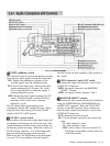
These output analog audio signals for the four
channels to external equipment.
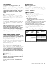
EARPHONE jack (stereo minijack)
Connect an earphone or stereo headphones equipped
with a stereo miniplug.
The MONITOR SELECT switches determine the
audio output.
When the WARNING indicator (see page 2-5) lights
or flashes, a warning sound is sent to the earphone.
HEADPHONES jack (stereo standard jack)
Connect stereo headphones with an impedance of 8
ohms.
The MONITOR SELECT switches determine the
audio output.
When the WARNING indicator (see page 2-5) lights
or flashes, a warning sound is sent to the headphones.
2-1 2 Chapter 2 Location and Function o( Parts