


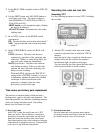
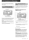
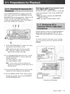
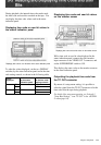
Use the MONITOR SELECT switches to select the
audio signals output from the EARPHONE jack and
HEADPHONES jack during playback. When the CH-
3/4 OUT switch is in the MON position, these
switches also select the audio output from channels 3
and 4 of the AUDIO OUT connectors.
Selecting the outputs from channels 3 and 4
of the AUDIO OUT connectors
Set the CH-3/4 OUT switch as follows: to select the
outputs from channels 3 and 4 of the AUDIO OUT
connectors.
MON: the signals selected by the MONITOR
SELECT switches
LINE: the signals of audio channels 3 and 4
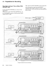
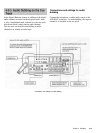
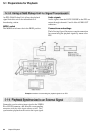
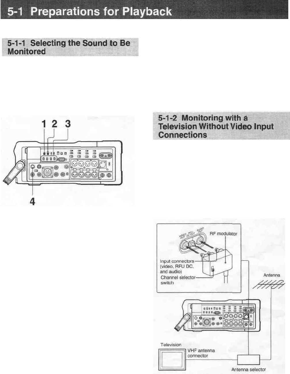
Connect the input connectors of an RF modulator to
the RF signal output connectors (RFU DC OUT,
VIDEO OUT and AUDIO OUT) on the connector
panel.
For details of channels and antenna selector switching,
refer to the operating instructions supplied with the RF
modulator.
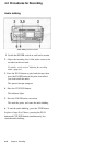
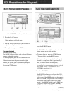
1 Of the MONITOR SELECT switches, first select
the position of the CUE/DA switch.
CUE: Monitor the audio from the cue track.
DA: Monitor the channels selected from the
digital audio recorded on the tape.
2 If you selected the DA position in step 1, set the
next MONITOR SELECT switch to choose the
channels monitored.
1/2: Audio channels 1 and 2
3/4: Audio channels 3 and 4
MIX: A mix of those of the four channels for
which the corresponding switches below are in
the ON position.
3 If you selected the MIX position in step 2, set the
switches on for the channels to be monitored.
4 Turn the PHONE LEVEL control knob to adjust
the audio level of the output to the EARPHONE
and HEADPHONES jacks.
Connections to an RF modulator
Chapters Playback 5-1