


27
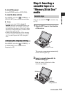
Basic Operations
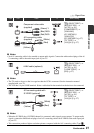
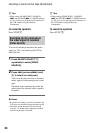
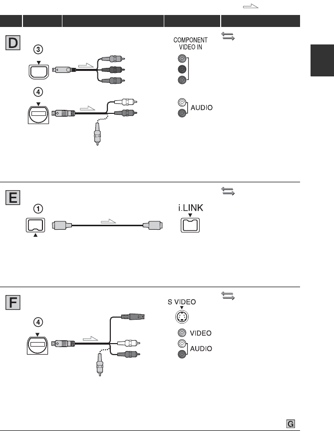
: Signal flow
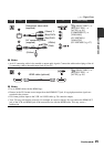
Type VCR Cable TV Menu Setting
(IN/OUT REC) t
[HDV/DV SEL] t
[AUTO] (p. 56)
[COMPONENT] t
[1080i/480i]
(GV-HD700/1)/
[1080i/576i]
(GV-HD700E/1) (p. 57)
[TV TYPE] t
[16:9]/[4:3] (p. 57)
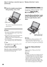
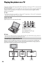
b Notes
• An A/V connecting cable is also needed to output audio signals. Connect the white and red plugs of the A/
V connecting cable to the audio input jack of your TV.
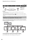
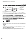
(IN/OUT REC) t
[HDV/DV SEL] t
[AUTO] (p. 56)
[i.LINK CONV] t
[ON] (p. 57)
b Notes
• The TV needs to be set so that it recognizes that the VCR is connected. See the instruction manual
supplied with your TV.
• The VCR has a 4-pin i.LINK terminal. Select a cable that fits the terminal on the device to be connected.
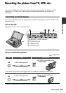
(IN/OUT REC) t
[HDV/DV SEL] t
[AUTO] (p. 56)
[TV TYPE] t
[16:9]/[4:3] (p. 57)
b Notes
• When the S VIDEO plug (S VIDEO channel) is connected, audio signals are not output. To output audio
signals, connect the white and red plugs of an A/V connecting cable with S VIDEO to the audio input jack
of your TV.
• This connection produces higher resolution pictures compared with the A/V connecting cable (Type ).
Component video cable
(supplied)
A/V connecting cable
(supplied)
(Green) Y
(Blue) P
B
/C
B
(Red) P
R
/C
R
(Red)
(White)
(Yellow)
i.LINK cable (optional)
A/V connecting cable with
S VIDEO (optional)
(Red)
(White)
(Yellow)
Continued ,