


Appendix
A-4 Appendix
Specifications
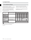
Processor adjustment range
Video level ±3 dB/ –∞ to +3 dB selectable
Chroma level ±3 dB/ –∞ to +3 dB selectable
Setup level (59.94i, 29.97PsF mode)
±30 IRE
Black level (50i, 25PsF mode)
±210 mV
Chroma phase ±30°
System phase Sync: ±15 µs
SC: ±200 ns
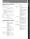
Input connectors
HDSDI INPUT BNC (1 each for input and for
through output to a monitor)
Serial digital (1.485 Gbits/s)
SMPTE 292M
SDTI INPUT BNC (1) (optional)
SMPTE 305M (SDTI)
REF. VIDEO INPUT
BNC (2 in loop through
connection)
Black burst or composite sync
0.3 Vp-p, 75 Ω, sync negative
AUDIO INPUT CH1/2/3/4
XLR 3-pin, female (4)
LOW OFF: –60 dBu, high
impedance, balanced
HIGH OFF: +4 dBu, high
impedance, balanced
HIGH ON: +4 dBm, 600 Ω
termination, balanced
CUE IN XLR 3-pin, female (1)
LOW OFF: –60 dBu, high
impedance, balanced
HIGH OFF: +4 dBu, high
impedance, balanced
HIGH ON: +4 dBm, 600 Ω
termination, balanced
AUDIO INPUT(AES/EBU) CH1/2, 3/4
BNC (2)
Complies with AES-3id-1995
TIME CODE IN XLR 3-pin, female (1)
0.5 to 18 Vp-p, 10 kΩ, balanced
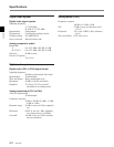
Output connectors
HDSDI OUTPUT
BNC (3 including 1 for character
superimposition)
Serial digital (1.485 Gbits/s)
SMPTE 292M
SDTI OUTPUT BNC (2) (optional)
SMPTE 305M (SDTI)
COMPONENT VIDEO OUTPUT
BNC (3 for 1 set)
Y: 1.0 Vp-p, Sync negative
R–Y/B–Y: 0.7 Vp-p, 75 Ω, with
100% or 75% color bar selectable
COMPOSITE VIDEO OUTPUT
BNC (3 including 1 for character
superimposition)
1.0 Vp-p, 75 Ω, Sync negative
SDI OUTPUT BNC (3 including 1 for character
superimpositon)
Serial digital (270 Mbits/s)
SMPTE 259M
AUDIO OUTPUT CH1/2/3/4
XLR 3-pin, male (4)
+4 dBm at 600 Ω load, low
impedance, balanced
CUE OUT XLR 3-pin, male (1)
+4 dBm at 600 Ω load, low
impedance, balanced
AUDIO OUTPUT (AES/EBU) CH1/2, 3/4, 5/6, 7/8
BNC (4)
Complies with AES-3id-1995
MONITOR OUTPUT (L/R)
XLR 3-pin, male (2)
+4 dBm at 600 Ω load, low
impedance, balanced
TIME CODE OUT
XLR 3-pin, male (1)
2.2 Vp-p, low impedance, balanced
PHONES JM-60 stereo phone jack
–∞ to –12 dBu at 8 Ω load,
unbalanced