


— 20 —
KV-27FV16/29FV16/29FV16C/32FS12/32FS16
SECTION 4
SAFETY RELATED ADJUSTMENTS
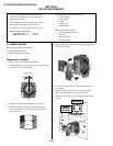
4-1.
R564 CONFIRMATION METHOD
(HV HOLD-DOWN CONFIRMATION) AND
READJUSTMENTS
The following adjustments should always be performed when
replacing the following components which are marked with
on
the schematic diagram:
Preparation Before Confirmation
1. Using a Variac, apply AC input voltage: 120 ± 2 VAC.
2. Turn the POWER switch ON.
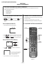
3. Input a white signal and set the PICTURE and
BRIGHTNESS controls to maximum.
4. Confirm that the voltage between C546 (+) or TP503
and ground is more than 21.0 VDC (KV-27FV16/29FV16/
29FV16C ONLY), 23.0 VDC (KV-32FS12/32FS16 ONLY).
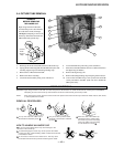
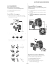
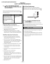
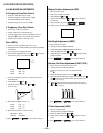
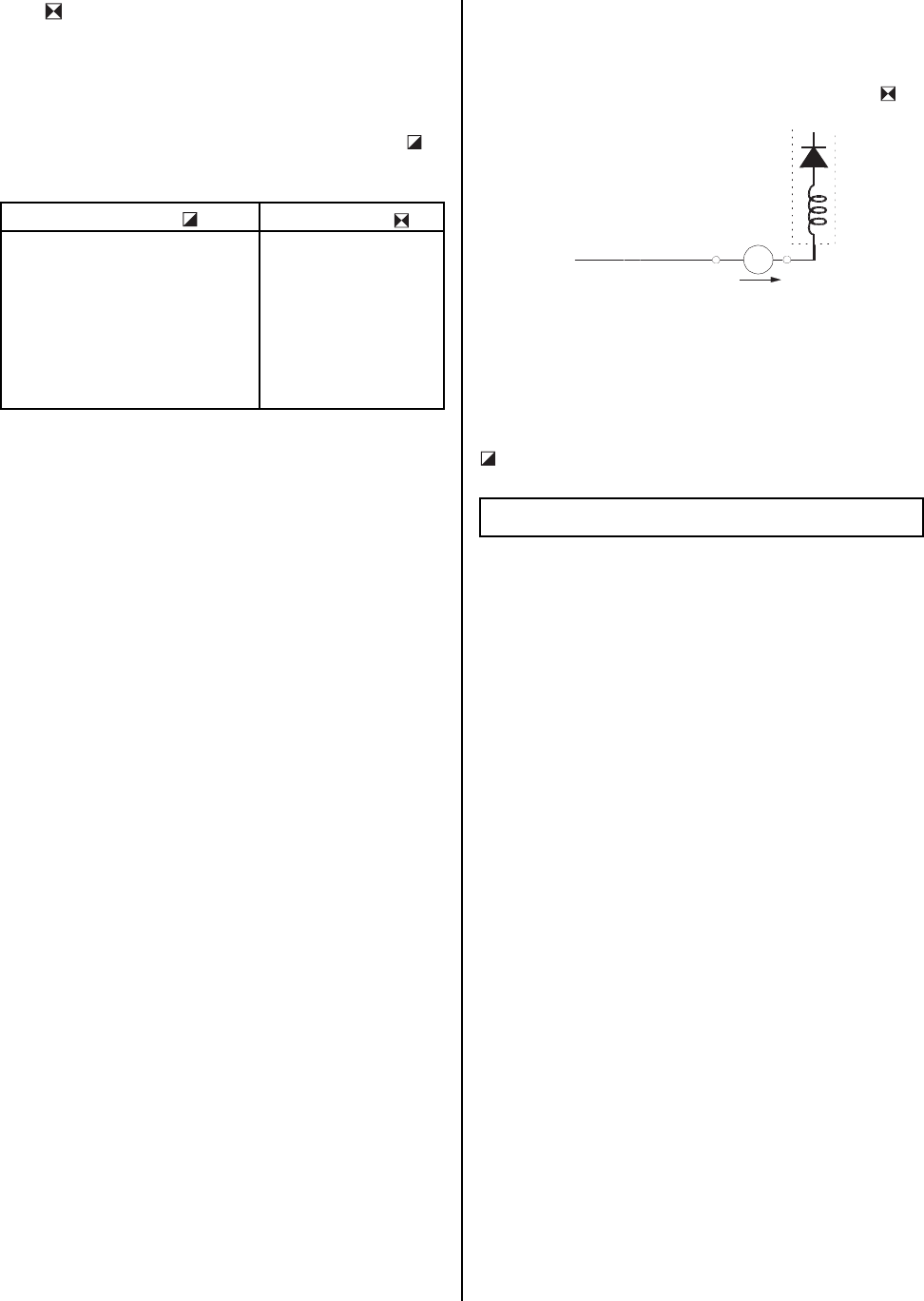
Hold-Down Operation Confirmation
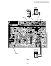
1. Connect the current meter between Pin 11 of the FBT
(T505) and the PWB land where Pin 11 would normally
attach. (See Figure 1 on the next page.)
2. Input a dot signal and set PICTURE and BRIGHTNESS
to minimum: IABL = 1730 ± 100 µA (KV-27FV16/29FV16/
29FV16C ONLY), IABL = 2175 + 100/- 325 µA (KV-
32FS12/32FS16 ONLY).
3. Confirm the voltage of A Board TP-600 is 135 ± 1.5 VDC.
4. Connect the digital voltmeter and the DC power supply
via diode 1SS119 to C546 (+) and ground. (See Figure 1
on the next page.)
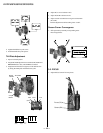
5. Increase the DC power voltage gradually until the picture
blanks out.
6. Turn DC power source off immediately.
7. Read the digital voltmeter indication
(standard < 24.78 +0.0/-0.1 VDC - KV-27FV16/29FV16/
29FV16C ONLY) (standard < 27.24 + 0.0/- 0.1 VDC - KV-
32FS12/32FS16 ONLY) .
8. Input a white signal and set PICTURE and BRIGHTNESS to
maximum: IABL = 1730 ± 100 µA (KV-27FV16/29FV16/
29FV16C ONLY), IABL = 2175 + 100/- 325 µA (KV-
32FS12/32FS16 ONLY).
9. Repeat steps 4 to 7.
Hold-Down Readjustment
If the setting indicated in step 2 of Hold-Down Operation
Confirmation cannot be met, readjustment should be performed by
altering the resistance value of R564 component marked with
.
+
IABL
ABL
T505
FBT
range
-
ammeter
3.0 mA DC
A
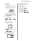
4-2. B+ VOLTAGE CONFIRMATION AND
ADJUSTMENT
Note: The following adjustments should always be performed
when replacing the following components, which are marked with
on the schematic diagram on the A Board.
A BOARD: IC601, PH601
1. Using a Variac, apply AC input voltage: 130 + 2.0/-0.0 VAC.
2. Input a monoscope pattern.
3. Set the PICTURE and BRIGHTNESS controls to minimum.
4. Confirm that the voltage of A Board TP-600 is <136.5 VDC.
5. If step 3 is not satisfied, replace the components listed above,
then repeat steps 1–3.
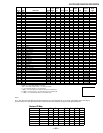
Part Replaced ( )
Adjustment (
)
DY, T505, CRT, IC501, C507,
C520, C505, C509, C515, T504,
T503, C551, L510, C546, C537,
C547, D517, D518, D519, R560,
R561, R562, R563, R565, R566,
R567, R525 ....................... A Board
IC301.............................. MA Board
HV HOLD-DOWN
R564