


— 7 —
KV-27FV16/29FV16/29FV16C/32FS12/32FS16
After correcting the original service problem, perform the
following safety checks before releasing the set to the
customer:
1. Check the area of your repair for unsoldered or poorly
soldered connections. Check the entire board surface
for solder splashes and bridges.
2. Check the interboard wiring to ensure that no wires are
“pinched” or touching high-wattage resistors.
3. Check that all control knobs, shields, covers, ground
straps, and mounting hardware have been replaced.
Be absolutely certain that you have replaced all the
insulators.
4. Look for unauthorized replacement parts, particularly
transistors, that were installed during a previous repair.
Point them out to the customer and recommend their
replacement.
5. Look for parts which, though functioning, show obvious
signs of deterioration. Point them out to the customer
and recommend their replacement.
6. Check the line cords for cracks and abrasion.
Recommend the replacement of any such line cord
to the customer.
7. Check the B+ and HV to see if they are specified
values. Make sure your instruments are accurate;
be suspicious of your HV meter if sets always have
low HV.
8. Check the antenna terminals, metal trim, “metallized”
knobs, screws, and all other exposed metal parts for AC
leakage. Check leakage as described below.
SAFETY CHECK-OUT
Leakage Test
The AC leakage from any exposed metal part to earth
ground and from all exposed metal parts to any exposed
metal part having a return to chassis, must not exceed 0.5
mA (500 microamperes). Leakage current can be
measured by any one of three methods.
1. A commercial leakage tester, such as the Simpson 229
or RCA WT-540A. Follow the manufacturers'
instructions to use these instructions.
2. A battery-operated AC milliammeter. The Data Precision
245 digital multimeter is suitable for this job.
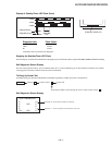
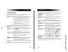
3. Measuring the voltage drop across a resistor by means
of a VOM or battery-operated AC voltmeter. The “limit”
indication is 0.75 V, so analog meters must have an
accurate low voltage scale. The Simpson’s 250 and
Sanwa SH-63TRD are examples of passive VOMs that
are suitable. Nearly all battery-operated digital
multimeters that have a 2 VAC range are suitable
(see Figure A).
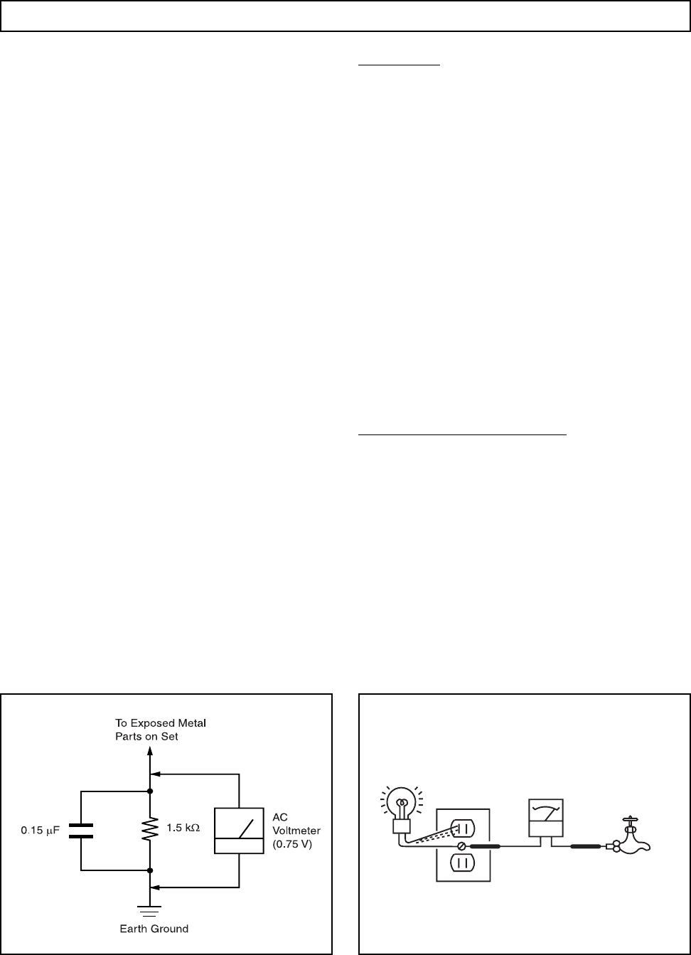
How to Find a Good Earth Ground
A cold-water pipe is a guaranteed earth ground; the cover-
plate retaining screw on most AC outlet boxes is also at earth
ground. If the retaining screw is to be used as your earth
ground, verify that it is at ground by measuring the resistance
between it and a cold-water pipe with an ohmmeter. The
reading should be zero ohms. If a cold-water pipe is not
accessible, connect a 60- to 100-watt trouble- light (not a
neon lamp) between the hot side of the receptacle and the
retaining screw. Try both slots, if necessary, to locate the hot
side on the line; the lamp should light at normal brilliance if the
screw is at ground potential (see Figure B).
Figure B. Checking for earth ground.Figure A. Using an AC voltmeter to check AC leakage.
Trouble Light
AC Outlet Box
Ohmmeter
Cold-water Pipe