


Installation
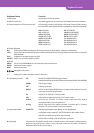
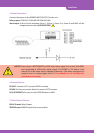
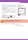
3. Alarm Connections
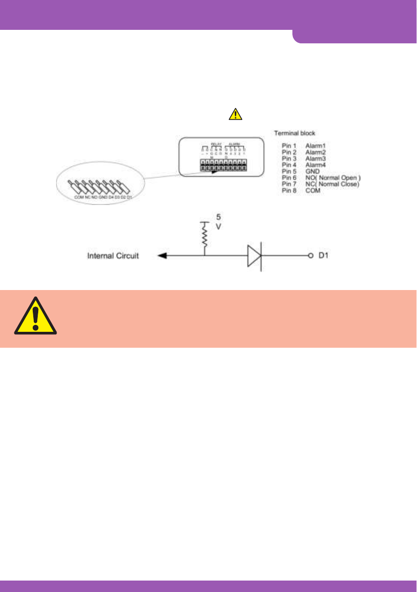
Connect the alarms to the SENSOR INPUT/OUTPUT on the unit.
Relay output:COM+NC, COM+NO OR COM+NC+NO
Alarm input:A short-circuit between Alarm 1, Alarm 2, Alarm 3 or Alarm 4 and GND will be
recognized as an alarm (VOLTAGE FREE) .
NOTICE:Alarm input is RECOGNIZED as LOW when alarm signal is on a level with GND,
and recognized as HIGH when alarm signal is FLOATING or 5V. Above is the
internal circuit. Be aware there is a danger of damage, if the alarm input goes to a
negative level or voltage higher than 5V. If exceeded this will invalidate the
manufacturer’s warranty.
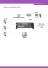
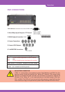
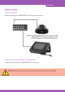
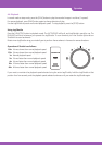
4. External Devices
RS-232C:Connect to PC to control DVRX remotely.
RS 485:On-Alarm connector block for control of PTZ cameras.
RJ-45 (ETHERNET):Connect to LAN, GPRS Modem or WAN.
5. Other External Devices
RELAY Output:Relay Output
SENSOR Input:SENSOR Input (Alarm connection)