


5-8
S
UPERSERVER 6015T-T/6015T-INF User's Manual
5-6 Installing Memory
1. Memory support
The X7DBT-T/X7DBT-INF has eight 240-pin DIMM sockets that can support up to
32 GB of ECC FBD (Fully Buffered DIMM) DDR2-667/533 SDRAM (for a total of
64 GB in the system). The memory scheme is interleaved, so you must populate
two slots at a time, beginning with slot 1A and 2A, then slots 3A and 4A and so on.
See chart below for optimizing your DIMM installation.
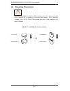
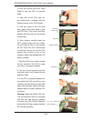
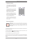
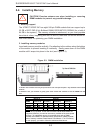
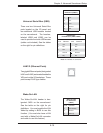
2. Installing memory modules
Insert each memory module vertically. Pay attention to the notches along the bottom
of the module to prevent inserting it incorrectly. Gently press down on the DIMM
module until it snaps into place in the slot (see Figure 5-3).
!
CAUTION! Exercise extreme care when installing or removing
DIMM modules to prevent any possible damage.
To Install: Insert module vertically and press down until it snaps into place. Pay attention to the bottom
notches.
To Remove: Use your thumbs to gently push each release tab outward to free the DIMM from the
slot.
Figure 5-3. DIMM Installation
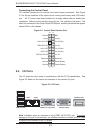
Optimized DIMM Configurations
Branch 0 Branch 1
Number of
DIMMs
Bank 1
(Channel 0)
Bank 2
(Channel 1)
Bank 3
(Channel 2)
Bank 4
(Channel 3)
2 DIMMs
1A
---
2A
--- --- --- --- ---
4 DIMMs 1A
---
2A
---
3A
---
4A
---
6 DIMMs 1A 1B 2A 2B 3A --- 4A ---
8 DIMMs 1A 1B 2A 2B 3A 3B 4A 4B
Notes: i. DIMM slot# specified = DIMM slot to be populated; “---“ = DIMM
slot not to be populated. ii. Both FBD 533 MHz and 667MHz DIMMs are
supported; however, you need to use memory modules of the same speed
and type. iii. Interleaved memory is supported when pairs of DIMM
modules are installed. To optimize memory performance, please populate
pairs of memory modules in both Branch 0 and Branch 1. iv. For memory
to work properly, you need to follow the restrictions listed above.