


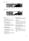
21
GGGGGGGG
GGGGGGGG
16
8
15
7
14
6
13
5
12
4
11
3
10
2
9
1
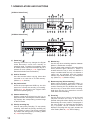
ALARM IN
IN
RM OUT-B
OUTIN GG
---+++GGGG
GGGG4321
NC
PRIORITY RM IN-BCAMERA
TIME SYNCCONTROL OUT
1615141312111098765432
LINK AUDIOMONITOR OUT RS-232C 100BASE-TX
RM IN-A
TERMINATION
ON
OFF
1
IN OUT21
IN
OUT
DISK ARRAY
2
VIDEO
AC MAINS
1
RM
GGGGGGGG
GGGGGGGG
16
8
15
7
14
6
13
5
12
4
11
3
10
2
9
1
ALARM IN
IN
RM OUT-B
OUTIN GG
---+++GGGG
GGGG4321
NC
PRIORITY RM IN-BCAMERA
TIME SYNCCONTROL OUT
1615141312111098765432
LINK AUDIOMONITOR OUT RS-232C 100BASE-TX
RM IN-A
TERMINATION
ON
OFF
1
IN OUT21
IN
OUT
DISK ARRAY
2
VIDEO
AC MAINS
1
RM
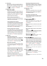
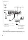
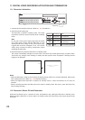
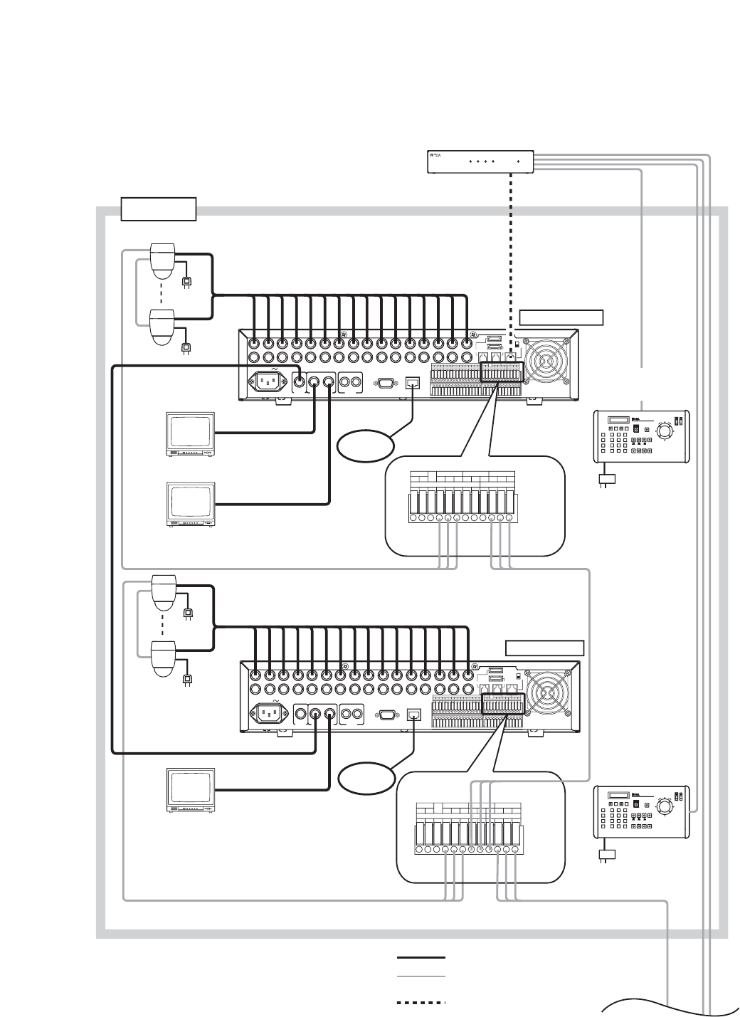
C-RF1000
DVR CONTROL
OUTPUT-A
REMOTE
CONTROLLER
INPUT-B
AC adaptor
RM IN-A
RM IN-B
RS-485
RS-485
Group 1
RM
OUT-B
Remote Controller 2
C-RM1000
Interface unit
Termination: OFF
Termination: OFF
Digital Video Recorder 1
C-DR161 Series
Monitor 1
Monitor 2
Live only
To AC Mains
Combination camera
RS-485
RS-485
CAMERA
+
G
-
10BASE-T/
100BASE-TX
CONTROL OUT TIME SYNC
CAMERA RM IN-BPRIORITY
NC
1234GGGG
GGGG
+++
---
GGIN OUT
RM OUT-B
IN
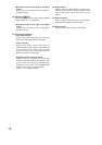
Monitor 2
Live only
RS-485
CAMERA
+
G
-
10BASE-T/
100BASE-TX
CONTROL OUT TIME SYNC
CAMERA RM IN-BPRIORITY
NC
1234GGGG
GGGG
+++
---
GGIN OUT
RM OUT-B
IN
LINK
RM
OUT-B
To next page
Remote Controller 1
C-RM1000
To LAN
To LAN
MONITOR
OUT 2
MONITOR
OUT 2
MONITOR
OUT 1
To AC Mains
Digital Video Recorder 2
C-DR161 Series
MONITOR
OUT 1
Group 1
Master
Monitor
REMOTE CONTROLLER
POWER/DVR4321
INTERFACE UNIT C-RF1000
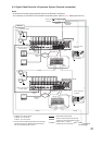
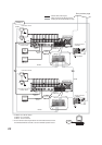
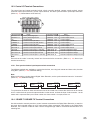
C-DR091 and C-DR161 Series
C-DR091: 9 I/ O Terminals
C-DR161: 16 I/ O Terminals
*
1
: CPEV-S 0.65-3C (RS-485 Control line)
Twisted pair with shield 22AWG or larger
: Modular cable, 3 m (9.8 ft)
(supplied with the C-RF1000)
: Coaxial cable (Video signal)
*
1
*
1
*
2
*
2
*
2
For the maximum cable length between the C-RF1000
Interface Unit and the C-RM1000 Remote Controller,
refer to C-RM1000 operation manual.
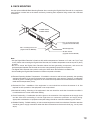
9.3. Digital Video Recorder’s Expansion System (Cascade connection)
Notes
• A cascade-connected system generally requires the Remote Controller(s).
• It is necessary to set DVR-ID in the cascade-connected system. (Refer to p. 27; Setting the DVR -ID.)