


25
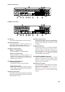
Terminal name
Name
PRIORITY IN
PRIORITY G
NC
CAMERA
+
CAMERA G
CAMERA
-
RM IN-B
+
RM IN-B G
RM IN-B
-
RM OUT-B
+
RM OUT-B G
RM OUT-B
-
Priority Recording Input
Priority Recording Ground
Not connected
Camera Control (RS-485) +
Camera Control (RS-485) Ground
Camera Control (RS-485)
-
Remote Control Input B + (RS-485)
Remote Control Input B Ground
Remote Control Input B
-
(RS-485)
Remote Control Output B + (RS-485)
Remote Control Output B Ground
Remote Control Output B
-
(RS-485)
Terminal name
Name
CONTROL OUT 1
CONTROL OUT G
CONTROL OUT 2
CONTROL OUT G
CONTROL OUT 3
CONTROL OUT G
CONTROL OUT 4
CONTROL OUT G
TIME SYNC IN
TIME SYNC G
TIME SYNC OUT
TIME SYNC G
Control Output 1
Control Output Ground
Control Output 2
Control Output Ground
Control Output 3
Control Output Ground
Control Output 4
Control Output Ground
Date/Time Adjustment Input
Date/Time Adjustment Input Ground
Date/Time Adjustment Output
Date/Time Adjustment Output Ground
A
B
IN
RM OUT-B
OUTIN GG
-
--
++
+
GGGG
GGGG4321
NC
PRIORITY RM IN-BCAMERA
TIME SYNCCONTROL OUT
A
B
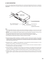
Master
Input Output
Slave 1
Input Output
Slave 2
Input Output
Slave 7
Input Output
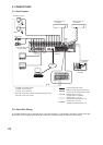
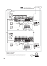
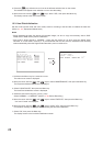
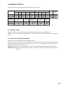
10.4. 10BASE-T/100BASE-TX Terminal Connections
Use this terminal to remotely monitor or control cameras connected to the Digital Video Recorder, or search or
play back their recorded images on a PC web browser. When connecting a PC directly to the Digital Video
Recorder, use a network crossover cable. Use the straight-through cable for connection between them via a
switching hub.
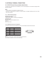
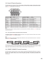
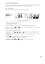
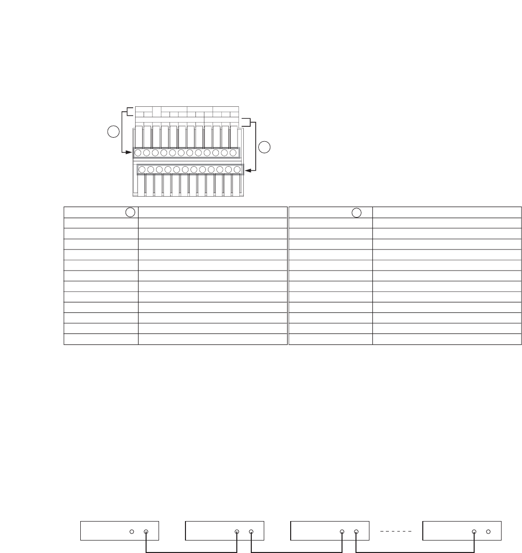
10.3. Control I/O Terminal Connections
The control input and output terminals include: priority recording terminal, camera control terminal, remote
controller input/output terminals, control output terminal, and time synchronization input/output terminals.
(Refer to p. 14; Nomenclature and Functions.)
Note
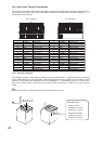
Ensure that the cable is securely locked into the terminal after connection. (Refer to p. 24; Alarm input
terminal connections.)
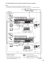
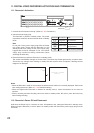
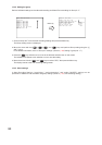
10.3.1. Time synchronization input/output terminal connections
Two different methods are available to synchronize the time, one using both master and slave units, the other
using NTP. (Refer to p. 100; Date/time setting.)
Note
When synchronizing a single-channel Digital Video Recorder, set the synchronization interval to “5 seconds.”
(Refer to p. 100; Date/time setting.)
To synchronize the times of slave units with the time of the master unit, connect the slave units to the master
unit in a series via their input and output terminals. In other words, connect the input of slave number 1 to the
master unit’s output and the input of slave number 2 to slave number 1’s output, and so on.