


26
Connections
EN
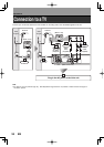
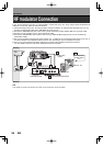
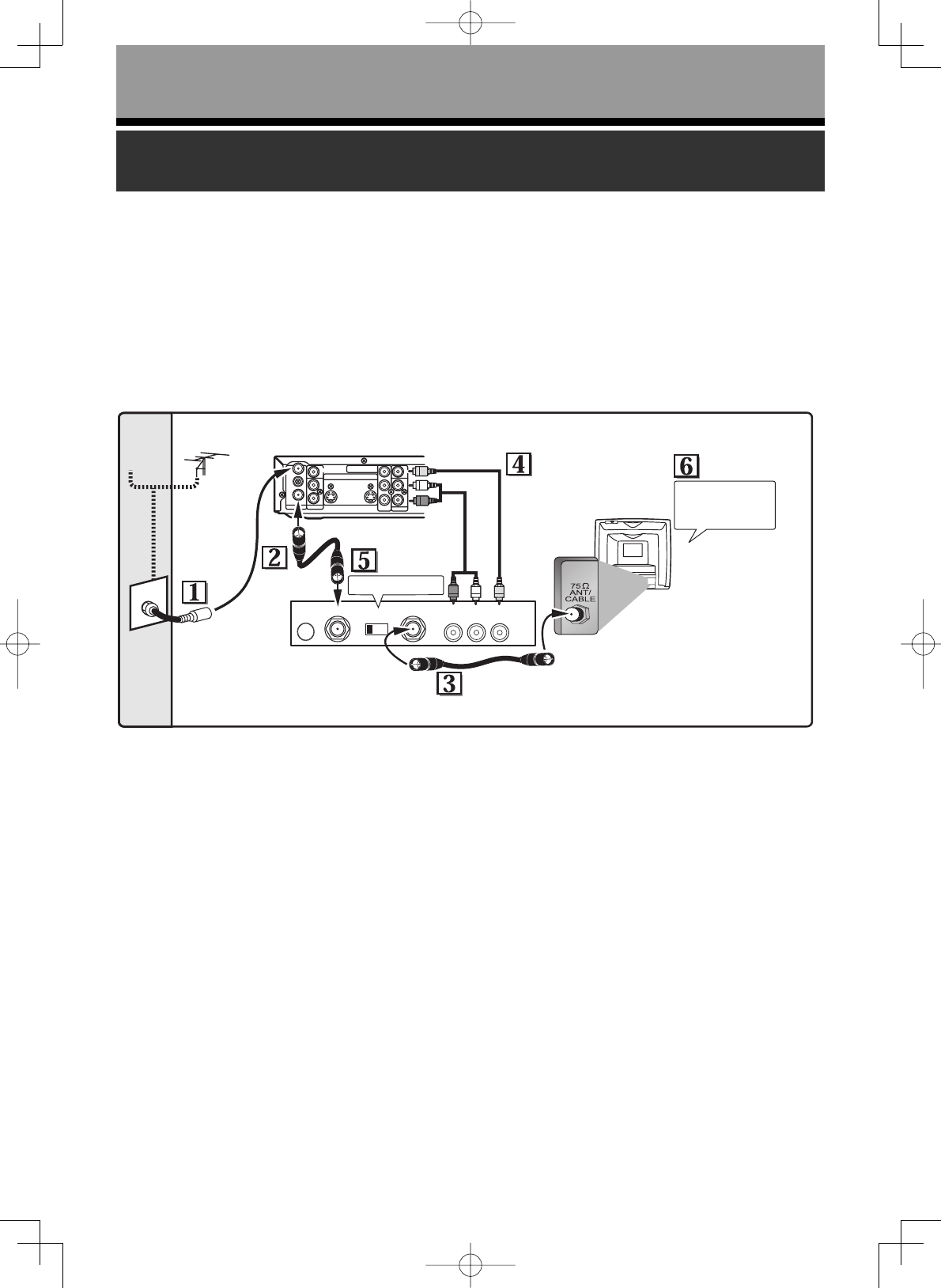
RF modulator Connection
TO TVCHANNEL VIDEO INAUDIO IN
RL34
ANT IN
AC 120V
ANTENNA
AUDIO IN
VIDEO IN
L
R
AUDIO OUT
VIDEO OUT
(L1)
IN
IN
OUT
OUT
S-VIDEO
COMPONENT
VIDEO OUTPUT
L
Y
P
B
/C
B
P
R
/C
R
R
Antenna
Cable TV
signal
(Back of this unit)
RF cable
(supplied)
Set channel 3 or 4.
STEREO AUDIO/VIDEO
RF Modulator
(commercially available)
Audio/Video cables
(supplied)
Antenna in jack
RF cable (commercially available)
Turn on your TV
and select channel
3 or 4.
(Back of TV)
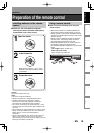
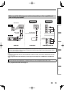
If your TV has Antenna in jack only, it is still possible to connect this unit to your TV by using a Stereo Audio/Video RF
modulator. In this case, follow the instructions below.
1) The antenna input jack of your TV may have been already occupied. If so, disconnect the RF cable from your TV,
and then connect the RF cable to the ANTENNA IN jack of this unit.
2) Connect the ANTENNA OUT jack of this unit to your RF modulator (usually marked “ANT IN”) by the RF cable.
3) Connect your RF modulator to your TV by another RF cable.
4) Connect the AUDIO/VIDEO output jacks of this unit to the AUDIO/VIDEO input jacks of your RF modulator by
Audio/Video cables.
5) Set your RF modulator’s channel 3/4 switch to either 3 or 4, whichever the TV channel is least used in your area. If
your RF modulator has a Modulator/Antenna switch, set it according to your RF modulator’s manual.
6) Turn on your TV and choose the same channel as you set the RF modulator’s channel 3/4 switch to.
For more details, follow the instructions supplied with the RF modulator.
Note
• The quality of picture may become poor if this unit is connected to an RF modulator.