


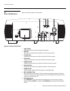
Controls and Functions
10 Vidikron Vision Model 120 Installation/Operation Manual
PRE
L
IMINAR
Y
2.4
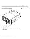
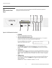
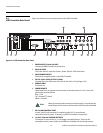
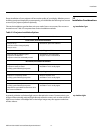
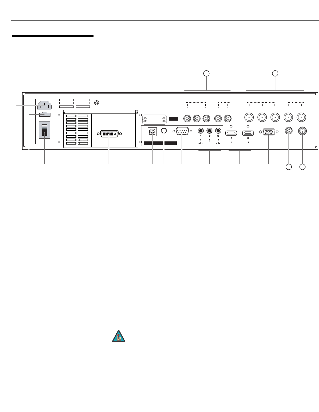
VHD Controller Rear Panel
Figure 2-4 shows the rear connector panel on the VHD Controller.
Figure 2-4. VHD Controller Rear Panel
1. POWER INPUT (100 to 240 VAC)
Connect the VHD Controller to power here.
2. MAIN AC FUSE
This is the main AC input fuse (5mm x 20mm, 500 mA, 250V slow-blow).
3. MAIN POWER SWITCH
Disconnects or applies power to the VHD Controller.
4. DVI-DL (DUAL-LINK) OUTPUT (1080p)
Connect this to the VHD Input at the rear of the Vision 120 (see Figure 2-2).
5. SERVICE ONLY
For future use.
6. WIRED REMOTE
Wired input from an external remote control or infrared receiver. It is a 3.5-mm, mini
phono jack, wired as follows:
Ring = +5V
Tip = IR Input (TTL level)
Sleeve = Ground
7. RS-232/485 CONTROL PORT
A male, 9-pin D-sub connector for interfacing with a PC or home theater
automation/control system. (Currently, only RS-232 interface is supported.)
8. 12-VOLT (750 mA) TRIGGER OUTPUTS
Connection for up to three (3), 12-volt trigger-controlled devices. These can be
retractable screens, screen masks or the Vidikron CineWide with AutoScope system.
II IIII
TRIGGERS
RS-232 / 485
WIRED
REMOTESERVICE ONLY
SYSTEM CONTROL INTERFACE
HD3 (VGA / Y-Pb-Pr) COMPOSITE S-VIDEO
HD2 (BNC)
VsHs
Pr / RPb / BY / G
HD1 (RCA)
Y / G
VsHs
Pr / RPb / B
HDMI
II I
INPUTS
Service port.
Not for user
access
11
1
23
4 5 67 8 9
12
13
14
When an external remote control or infrared receiver is connected to the
wired IR input, the IR sensor on the front of the VHD Controller is disabled.
Note