


Vidikron Vision Model 65/Model 75 Installation/Operation Manual 5
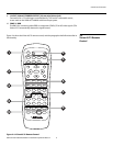
2.1
Vision 65/75 at a Glance
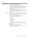
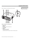
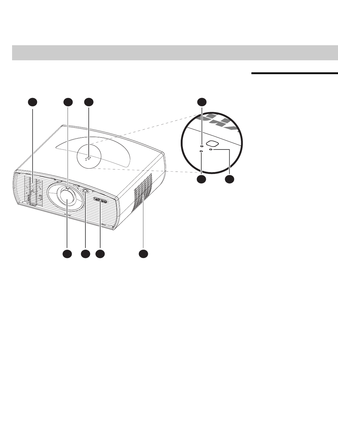
Figure 2-1 and Figure 2-2 show the key Vision 65/75 components.
Figure 2-1. Vision 65/75 Front/Side/Top View
1. EXHAUST VENT
2. ZOOM TAB
Use this to change the projected image size.
3. TOP IR SENSOR
4. LAMP LED
Indicates lamp status as follows:
• Off during normal operation
• Red when the lamp has exceeded its usage life or developed a problem
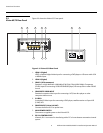
2Controls and Functions
12
78910
5 6
43