WB-31
Page 8 Installation Instructions
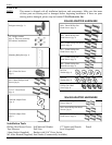
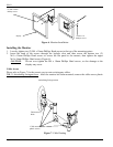
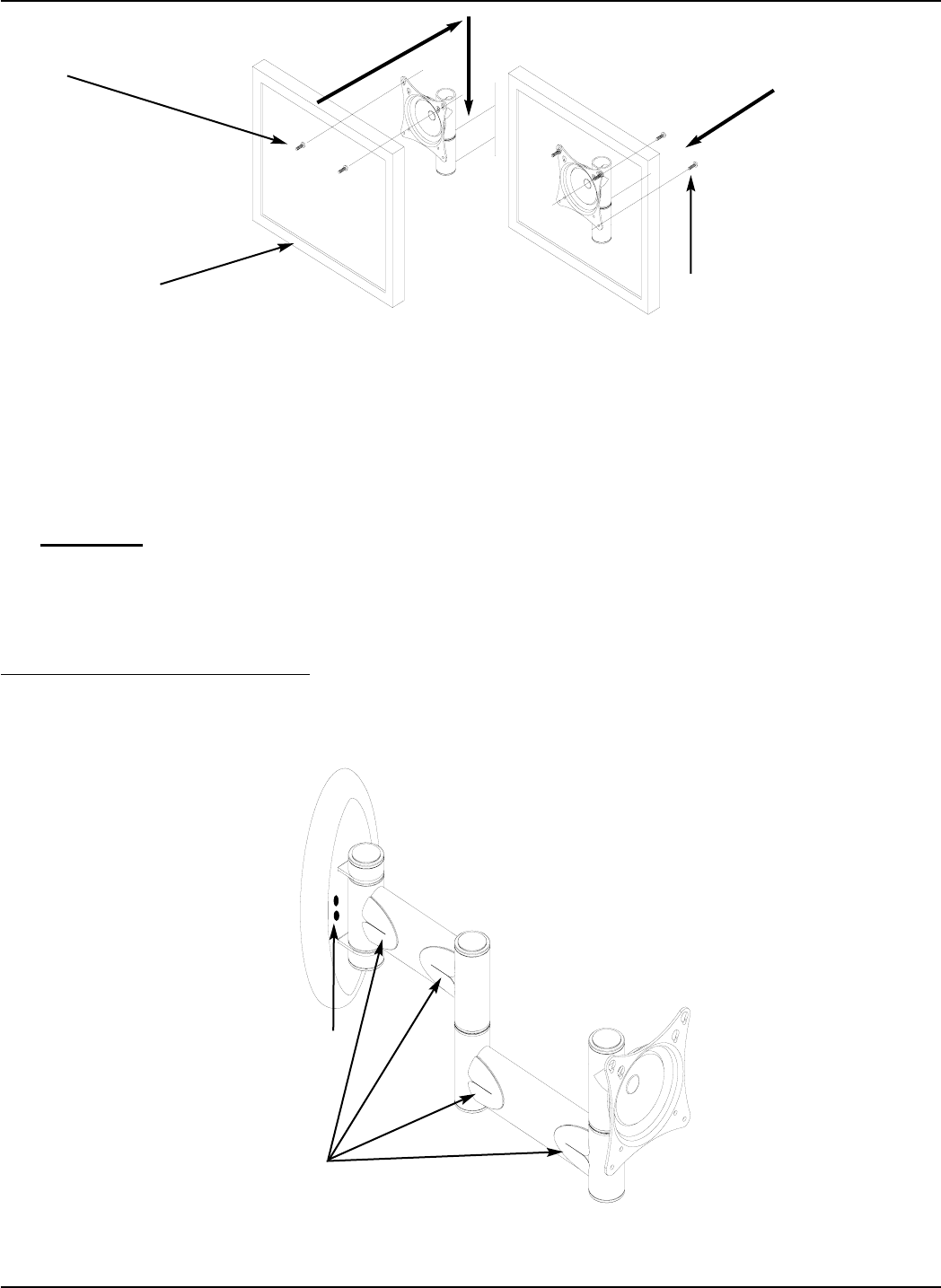
Figure 7. Cable Routing
Installing the Monitor
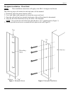
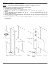
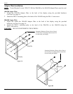
1. Loosely tighten two (2) M4 x 10mm Phillips Head screws to the top of the mounting points.
2. Insert the head of the screws through the keyhole slots and then secure the bottom two (2)
M4 x 10mm Phillips Head screws to secure the flat panel to the mounts, then tighten the upper
M4 x 10mm Phillips Head screws (Figure 6).
CAUTION
: Do not over tighten the M4 x 10mm Phillips Head screws, or else damage to the
display may occur.
Cable Access
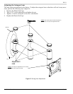
Please refer to Figure 7 for the correct way to route existing any cables.
WB-31
Articulating Swingout
Arm - After the monitor has been mounted, remove the cable access plastic
Cable access
plastic covers
Display
(2) M4 x 10mm
Phillips screws
(2) M4 x 10
Phillips screws
Figure 6. Monitor Installation
Cable access
holes
Articulating Swingout Arm


