


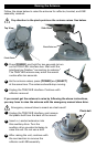
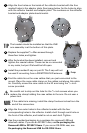
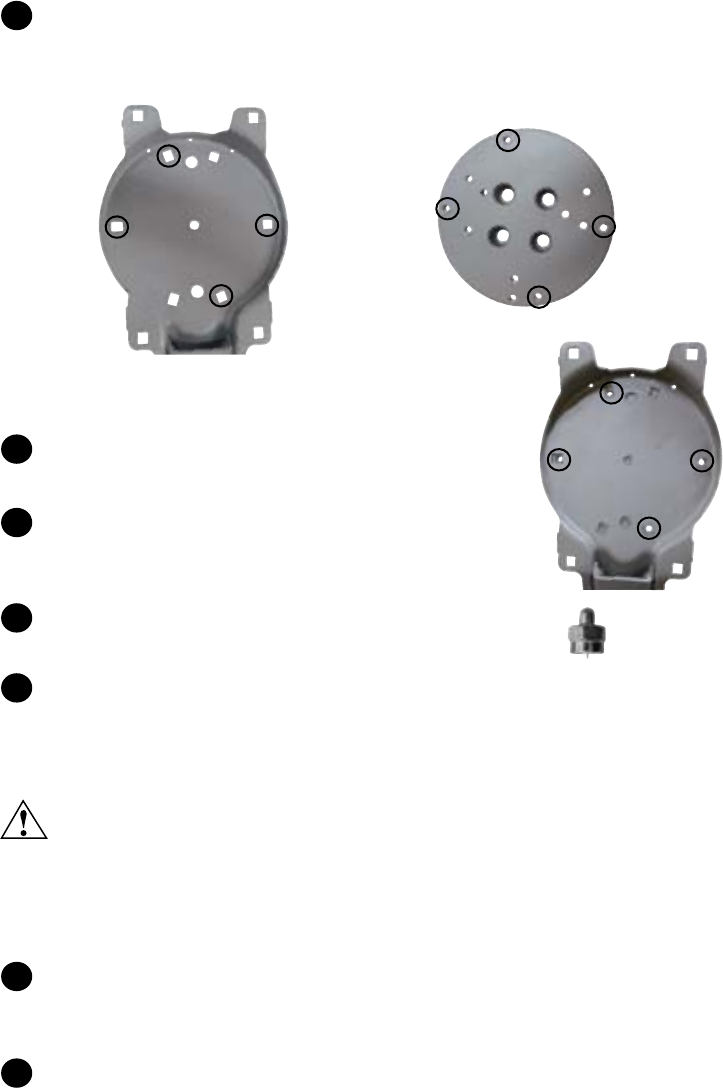
Align the four holes on the inside of the reflector bracket with the four
marked holes in the adaptor plate. See image below for the holes to align
with the reflector bracket and adaptor plate. The numbers on the reflector
bracket and adaptor plate should match.
TIP
The bracket should be installed so that the LNB
arm assembly is at the bottom of this plate.
Replace the supplied
3
/
16
Allen screws through
these four holes, and tighten.
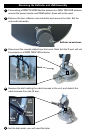
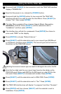
After the bracket has been installed, connect and
tighten the coaxial cables. These can be re-connected
in any order, but port D should be left open.
Install the provided F-cap on port D. The F-cap will not
be used if converting from a SWM TRAV’LER antenna.
Find the cable tie on the coax cables that you just connected to the
mount. Place the coax cable clamp on the cables just above this cable
tie. Carefully screw this coax cable to the lift arm using the
5
/
16
inch
screw provided.
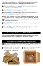
Be careful not to strip out the hole for the
5
/
16
inch screws when you
replace the clamp holding the coax cables to the arm. Do not user a
power tool.
NOTE
If the cable tie is missing, install the clamp fourteen inches from the
end of the connectors.
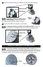
Align the four outer holes in the reflector bracket with the four
corresponding holes in the reflector. Install a bolt through each hole on
the front of the reflector, and install a nut on each bolt. Tighten.
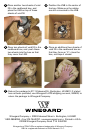
Use the provided packaging to re-package the removed LNB and
attached cables. If you are an RP-SK21 user, see Re-packaging the
Removed LNB for RP-SK21 Users. If you are an OE-DISH user, see
Re-packaging the Removed LNB for OE-DISH Users.
1
2
3
4
F-cap
5
6
7
1
1
2
3
4
2
3
4
1
2
3
4