Scanner Interface
Appendix A-42
a. Allocation length: Byte 4
Specifies the storage area in bytes that the initiator allocates for sense data. If a 0 is set here,
sense data is not transferred, but this is not treated as an error. The target terminates the
DATA IN phase when it has transferred either the bytes of sense data specified in this field or
all of effective sense data.
(2) Sense data: DATA IN phase (target → initiator)
The target creates sense data if its status is B’00001’ (CHECK CONDITION) or if a BUS FREE
error has occurred. This scanner creates sense data when any of the errors described later is
encountered.
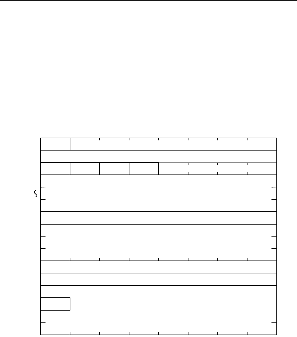
The sense data on this scanner is shown in the following illustration.
a. Valid: Byte 0
Indicates whether or not the INFORMATION BYTES field is as specified by ANSI. This
scanner returns B’1’ (“specified by ANSI”).
Byte 0
Segment number
Command-specific information byte
(LSB)
Sense-key specific bytes
(Reserved)
Information bytes
(LSB)
Additional sense length
Additional sense code
Additional sense code qualifier
Field replaceable unit code


